
GXT2-10000RT208 specifications
The Liebert GXT2-10000RT208 is a highly sophisticated uninterruptible power supply (UPS) designed to deliver reliable power protection for critical IT infrastructure and business operations. With a power capacity of 10,000 VA, this UPS ensures the continuous operation of essential devices, safeguarding them from potential damage caused by power interruptions, surges, or sags.One of the standout features of the Liebert GXT2-10000RT208 is its online double conversion technology. This technology provides a consistent, high-quality power output by converting incoming AC power to DC and then back to AC. This process eliminates voltage fluctuations and offers a stable energy supply, ensuring that connected equipment operates smoothly, regardless of the condition of the utility power.
The UPS is designed to support a wide range of applications, making it an ideal choice for data centers, telecommunications setups, and other critical environments. Its advanced microprocessor control ensures precise monitoring and regulation of power conditions. The Liebert GXT2-10000RT208 also features an impressive input voltage range, which is beneficial in areas where power quality is inconsistent.
Equipped with an LCD display, users can easily access vital information regarding the UPS’s operational status, battery health, and power protection levels. This user-friendly interface simplifies monitoring and management, allowing for quick assessments and troubleshooting.
Another key characteristic of the Liebert GXT2-10000RT208 is its modular design. This allows for easy installation and maintenance, as well as the opportunity to expand the power capacity by adding external battery cabinets. This scalability ensures that businesses can adapt their power protection solutions to meet evolving needs without significant changes to their existing setups.
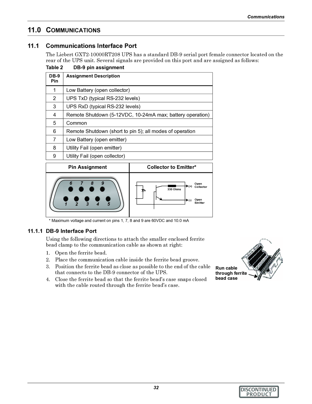
The UPS also includes advanced battery management features that optimize battery lifespan and performance. The Liebert GXT2-10000RT208 employs intelligent charging algorithms and battery testing functions to ensure reliable performance when needed most. Furthermore, support for various communication protocols enhances compatibility with other management systems, enabling seamless integration into existing infrastructure.
In summary, the Liebert GXT2-10000RT208 is a powerful and versatile UPS solution that combines advanced technology with robust features. Its online double conversion technology, extensive monitoring capabilities, and scalable design make it an excellent choice for organizations seeking reliable protection for their critical systems. With the GXT2-10000RT208, businesses can operate confidently, knowing their power supply is secure from unexpected disruptions.