BURNER IGNITOR
1.Shut off power at main breaker.
2.Remove control panel top and front cover.
3.Remove burner assembly. (SEE "BURNER ASSY.")
4.Remove pilot shield and pilot shield extension.
5.Remove burner igniter.
6.Reassemble in reverse order (spark gap approx. .100 in. 2.5 mm) NOTE: Be sure to reconnect burner igniter cable to ignition control.
THERMOCOUPLE - REPLACEMENT
1.Shut off power at main breaker.
2.Remove control panel top and front cover.
3.Slide thermocouple out of oven chamber.
NOTE: Remove conveyor and bottom fingers to aid in removal and installation of thermocouple.
4.Remove two (2) wires from temperature control. Make note of wire numbers or color and location for reinstallation.
5.Reassemble in reverse order making sure the metal end on the thermocouple is securely held in the wire form in the oven chamber.
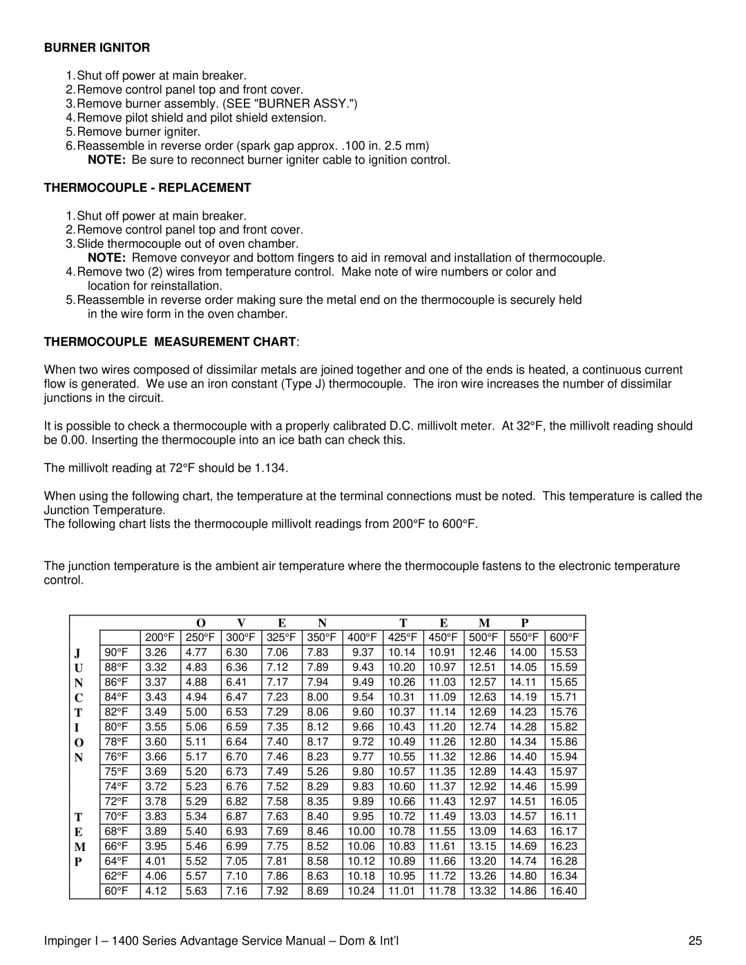
THERMOCOUPLE MEASUREMENT CHART:
When two wires composed of dissimilar metals are joined together and one of the ends is heated, a continuous current flow is generated. We use an iron constant (Type J) thermocouple. The iron wire increases the number of dissimilar junctions in the circuit.
It is possible to check a thermocouple with a properly calibrated D.C. millivolt meter. At 32°F, the millivolt reading should be 0.00. Inserting the thermocouple into an ice bath can check this.
The millivolt reading at 72°F should be 1.134.
When using the following chart, the temperature at the terminal connections must be noted. This temperature is called the Junction Temperature.
The following chart lists the thermocouple millivolt readings from 200°F to 600°F.
The junction temperature is the ambient air temperature where the thermocouple fastens to the electronic temperature control.
|
|
|
| O | V | E | N |
| T | E | M | P |
|
|
|
|
| 200°F | 250°F | 300°F | 325°F | 350°F | 400°F | 425°F | 450°F | 500°F | 550°F | 600°F |
|
| J | 90°F | 3.26 | 4.77 | 6.30 | 7.06 | 7.83 | 9.37 | 10.14 | 10.91 | 12.46 | 14.00 | 15.53 |
|
| U | 88°F | 3.32 | 4.83 | 6.36 | 7.12 | 7.89 | 9.43 | 10.20 | 10.97 | 12.51 | 14.05 | 15.59 |
|
| N | 86°F | 3.37 | 4.88 | 6.41 | 7.17 | 7.94 | 9.49 | 10.26 | 11.03 | 12.57 | 14.11 | 15.65 |
|
| C | 84°F | 3.43 | 4.94 | 6.47 | 7.23 | 8.00 | 9.54 | 10.31 | 11.09 | 12.63 | 14.19 | 15.71 |
|
| T | 82°F | 3.49 | 5.00 | 6.53 | 7.29 | 8.06 | 9.60 | 10.37 | 11.14 | 12.69 | 14.23 | 15.76 |
|
| I | 80°F | 3.55 | 5.06 | 6.59 | 7.35 | 8.12 | 9.66 | 10.43 | 11.20 | 12.74 | 14.28 | 15.82 |
|
| O | 78°F | 3.60 | 5.11 | 6.64 | 7.40 | 8.17 | 9.72 | 10.49 | 11.26 | 12.80 | 14.34 | 15.86 |
|
| N | 76°F | 3.66 | 5.17 | 6.70 | 7.46 | 8.23 | 9.77 | 10.55 | 11.32 | 12.86 | 14.40 | 15.94 |
|
|
| 75°F | 3.69 | 5.20 | 6.73 | 7.49 | 5.26 | 9.80 | 10.57 | 11.35 | 12.89 | 14.43 | 15.97 |
|
|
| 74°F | 3.72 | 5.23 | 6.76 | 7.52 | 8.29 | 9.83 | 10.60 | 11.37 | 12.92 | 14.46 | 15.99 |
|
|
| 72°F | 3.78 | 5.29 | 6.82 | 7.58 | 8.35 | 9.89 | 10.66 | 11.43 | 12.97 | 14.51 | 16.05 |
|
| T | 70°F | 3.83 | 5.34 | 6.87 | 7.63 | 8.40 | 9.95 | 10.72 | 11.49 | 13.03 | 14.57 | 16.11 |
|
| E | 68°F | 3.89 | 5.40 | 6.93 | 7.69 | 8.46 | 10.00 | 10.78 | 11.55 | 13.09 | 14.63 | 16.17 |
|
| M | 66°F | 3.95 | 5.46 | 6.99 | 7.75 | 8.52 | 10.06 | 10.83 | 11.61 | 13.15 | 14.69 | 16.23 |
|
| P | 64°F | 4.01 | 5.52 | 7.05 | 7.81 | 8.58 | 10.12 | 10.89 | 11.66 | 13.20 | 14.74 | 16.28 |
|
|
| 62°F | 4.06 | 5.57 | 7.10 | 7.86 | 8.63 | 10.18 | 10.95 | 11.72 | 13.26 | 14.80 | 16.34 |
|
|
| 60°F | 4.12 | 5.63 | 7.16 | 7.92 | 8.69 | 10.24 | 11.01 | 11.78 | 13.32 | 14.86 | 16.40 |
|
Impinger I – 1400 Series Advantage Service Manual – Dom & Int’l |
|
|
| 25 | ||||||||||