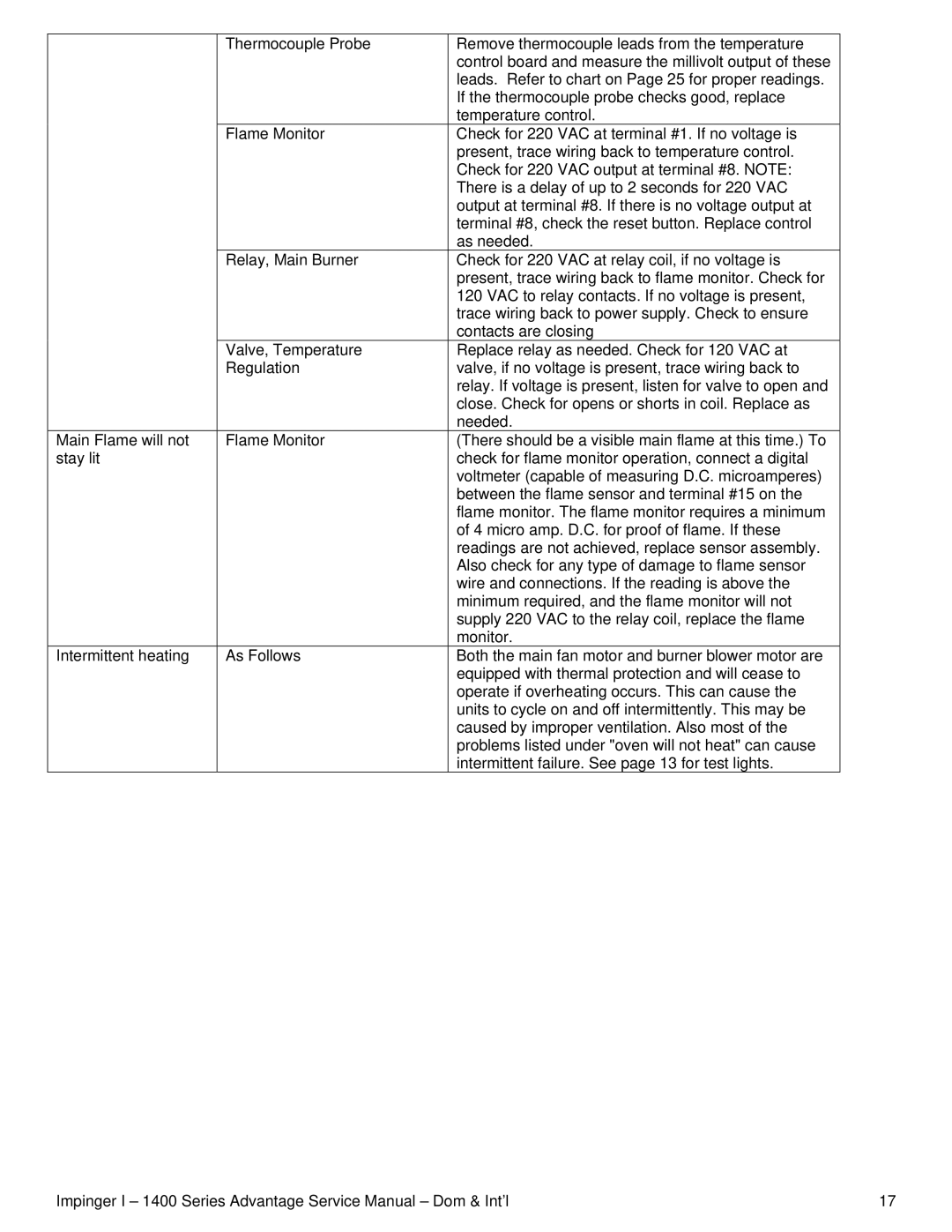
| Thermocouple Probe | Remove thermocouple leads from the temperature |
|
| control board and measure the millivolt output of these |
|
| leads. Refer to chart on Page 25 for proper readings. |
|
| If the thermocouple probe checks good, replace |
|
| temperature control. |
| Flame Monitor | Check for 220 VAC at terminal #1. If no voltage is |
|
| present, trace wiring back to temperature control. |
|
| Check for 220 VAC output at terminal #8. NOTE: |
|
| There is a delay of up to 2 seconds for 220 VAC |
|
| output at terminal #8. If there is no voltage output at |
|
| terminal #8, check the reset button. Replace control |
|
| as needed. |
| Relay, Main Burner | Check for 220 VAC at relay coil, if no voltage is |
|
| present, trace wiring back to flame monitor. Check for |
|
| 120 VAC to relay contacts. If no voltage is present, |
|
| trace wiring back to power supply. Check to ensure |
|
| contacts are closing |
| Valve, Temperature | Replace relay as needed. Check for 120 VAC at |
| Regulation | valve, if no voltage is present, trace wiring back to |
|
| relay. If voltage is present, listen for valve to open and |
|
| close. Check for opens or shorts in coil. Replace as |
|
| needed. |
Main Flame will not | Flame Monitor | (There should be a visible main flame at this time.) To |
stay lit |
| check for flame monitor operation, connect a digital |
|
| voltmeter (capable of measuring D.C. microamperes) |
|
| between the flame sensor and terminal #15 on the |
|
| flame monitor. The flame monitor requires a minimum |
|
| of 4 micro amp. D.C. for proof of flame. If these |
|
| readings are not achieved, replace sensor assembly. |
|
| Also check for any type of damage to flame sensor |
|
| wire and connections. If the reading is above the |
|
| minimum required, and the flame monitor will not |
|
| supply 220 VAC to the relay coil, replace the flame |
|
| monitor. |
Intermittent heating | As Follows | Both the main fan motor and burner blower motor are |
|
| equipped with thermal protection and will cease to |
|
| operate if overheating occurs. This can cause the |
|
| units to cycle on and off intermittently. This may be |
|
| caused by improper ventilation. Also most of the |
|
| problems listed under "oven will not heat" can cause |
|
| intermittent failure. See page 13 for test lights. |
Impinger I – 1400 Series Advantage Service Manual – Dom & Int’l | 17 |
