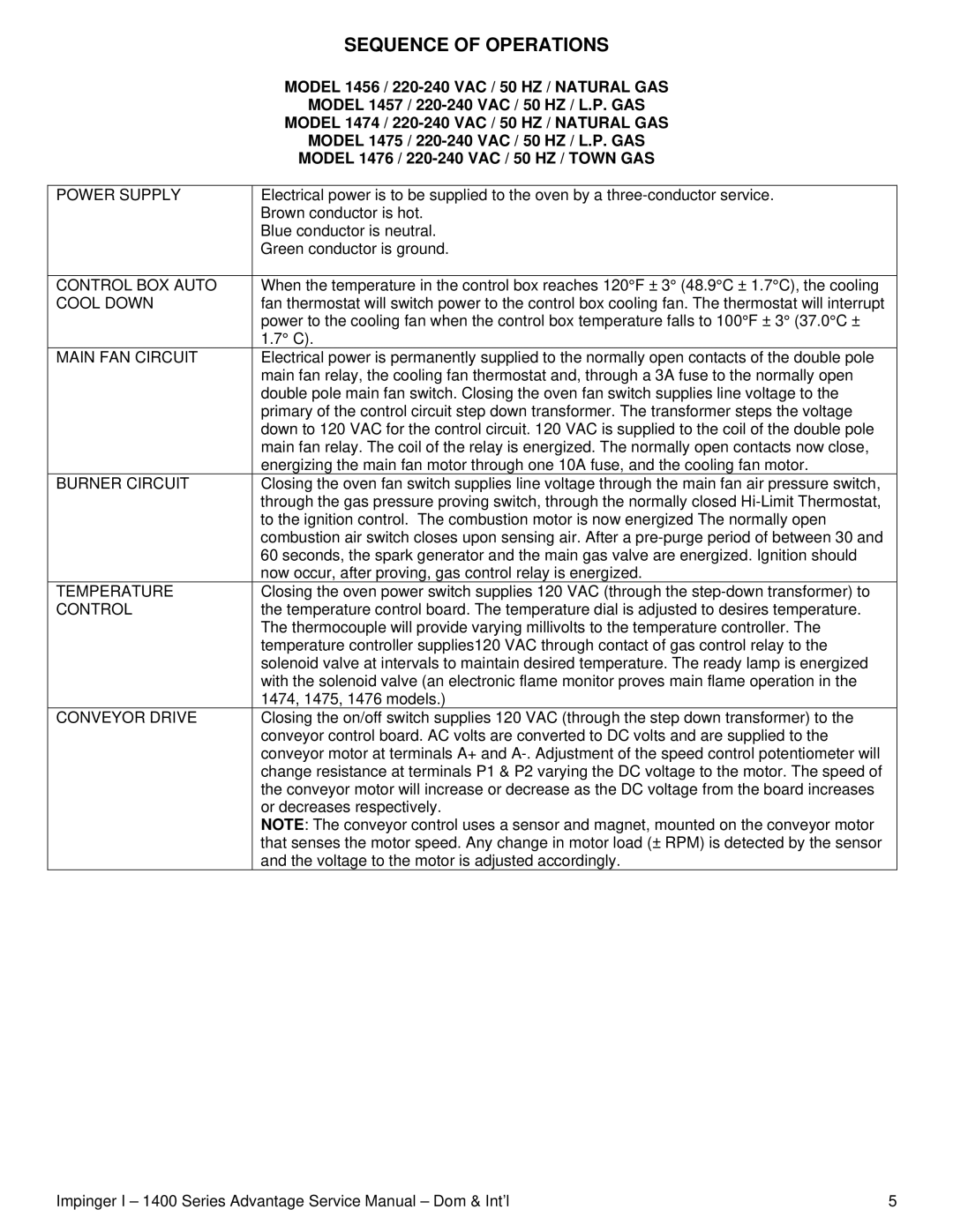
POWER SUPPLY
CONTROL BOX AUTO COOL DOWN
MAIN FAN CIRCUIT
BURNER CIRCUIT
TEMPERATURE
CONTROL
CONVEYOR DRIVE
SEQUENCE OF OPERATIONS
MODEL 1456 /
MODEL 1457 /
MODEL 1474 /
MODEL 1475 /
MODEL 1476 /
Electrical power is to be supplied to the oven by a
Blue conductor is neutral. Green conductor is ground.
When the temperature in the control box reaches 120°F ± 3° (48.9°C ± 1.7°C), the cooling fan thermostat will switch power to the control box cooling fan. The thermostat will interrupt power to the cooling fan when the control box temperature falls to 100°F ± 3° (37.0°C ± 1.7° C).
Electrical power is permanently supplied to the normally open contacts of the double pole main fan relay, the cooling fan thermostat and, through a 3A fuse to the normally open double pole main fan switch. Closing the oven fan switch supplies line voltage to the primary of the control circuit step down transformer. The transformer steps the voltage down to 120 VAC for the control circuit. 120 VAC is supplied to the coil of the double pole main fan relay. The coil of the relay is energized. The normally open contacts now close, energizing the main fan motor through one 10A fuse, and the cooling fan motor.
Closing the oven fan switch supplies line voltage through the main fan air pressure switch, through the gas pressure proving switch, through the normally closed
Closing the oven power switch supplies 120 VAC (through the
Closing the on/off switch supplies 120 VAC (through the step down transformer) to the conveyor control board. AC volts are converted to DC volts and are supplied to the conveyor motor at terminals A+ and
NOTE: The conveyor control uses a sensor and magnet, mounted on the conveyor motor that senses the motor speed. Any change in motor load (± RPM) is detected by the sensor and the voltage to the motor is adjusted accordingly.
Impinger I – 1400 Series Advantage Service Manual – Dom & Int’l | 5 |
