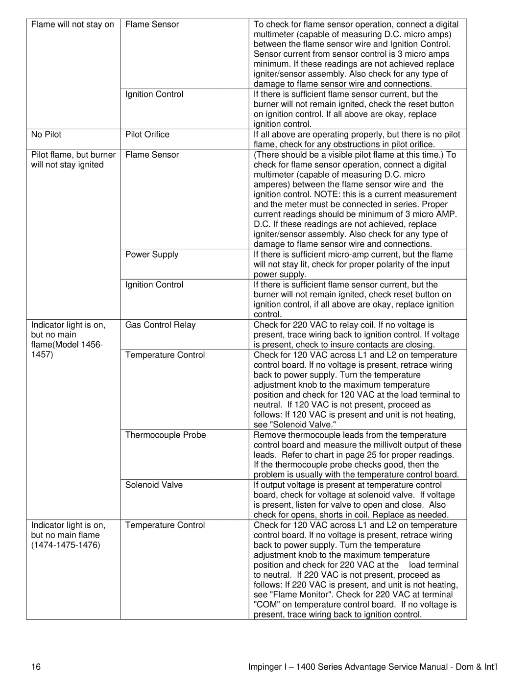
Flame will not stay on | Flame Sensor | To check for flame sensor operation, connect a digital |
|
| multimeter (capable of measuring D.C. micro amps) |
|
| between the flame sensor wire and Ignition Control. |
|
| Sensor current from sensor control is 3 micro amps |
|
| minimum. If these readings are not achieved replace |
|
| igniter/sensor assembly. Also check for any type of |
|
| damage to flame sensor wire and connections. |
| Ignition Control | If there is sufficient flame sensor current, but the |
|
| burner will not remain ignited, check the reset button |
|
| on ignition control. If all above are okay, replace |
|
| ignition control. |
No Pilot | Pilot Orifice | If all above are operating properly, but there is no pilot |
|
| flame, check for any obstructions in pilot orifice. |
Pilot flame, but burner | Flame Sensor | (There should be a visible pilot flame at this time.) To |
will not stay ignited |
| check for flame sensor operation, connect a digital |
|
| multimeter (capable of measuring D.C. micro |
|
| amperes) between the flame sensor wire and the |
|
| ignition control. NOTE: this is a current measurement |
|
| and the meter must be connected in series. Proper |
|
| current readings should be minimum of 3 micro AMP. |
|
| D.C. If these readings are not achieved, replace |
|
| igniter/sensor assembly. Also check for any type of |
|
| damage to flame sensor wire and connections. |
| Power Supply | If there is sufficient |
|
| will not stay lit, check for proper polarity of the input |
|
| power supply. |
| Ignition Control | If there is sufficient flame sensor current, but the |
|
| burner will not remain ignited, check reset button on |
|
| ignition control, if all above are okay, replace ignition |
|
| control. |
Indicator light is on, | Gas Control Relay | Check for 220 VAC to relay coil. If no voltage is |
but no main |
| present, trace wiring back to ignition control. If voltage |
flame(Model 1456- |
| is present, check to insure contacts are closing. |
1457) | Temperature Control | Check for 120 VAC across L1 and L2 on temperature |
|
| control board. If no voltage is present, retrace wiring |
|
| back to power supply. Turn the temperature |
|
| adjustment knob to the maximum temperature |
|
| position and check for 120 VAC at the load terminal to |
|
| neutral. If 120 VAC is not present, proceed as |
|
| follows: If 120 VAC is present and unit is not heating, |
|
| see "Solenoid Valve." |
| Thermocouple Probe | Remove thermocouple leads from the temperature |
|
| control board and measure the millivolt output of these |
|
| leads. Refer to chart in page 25 for proper readings. |
|
| If the thermocouple probe checks good, then the |
|
| problem is usually with the temperature control board. |
| Solenoid Valve | If output voltage is present at temperature control |
|
| board, check for voltage at solenoid valve. If voltage |
|
| is present, listen for valve to open and close. Also |
|
| check for opens, shorts in coil. Replace as needed. |
Indicator light is on, | Temperature Control | Check for 120 VAC across L1 and L2 on temperature |
but no main flame |
| control board. If no voltage is present, retrace wiring |
| back to power supply. Turn the temperature | |
|
| adjustment knob to the maximum temperature |
|
| position and check for 220 VAC at the load terminal |
|
| to neutral. If 220 VAC is not present, proceed as |
|
| follows: If 220 VAC is present, and unit is not heating, |
|
| see "Flame Monitor". Check for 220 VAC at terminal |
|
| "COM" on temperature control board. If no voltage is |
|
| present, trace wiring back to ignition control. |
16 | Impinger I – 1400 Series Advantage Service Manual - Dom & Int’l |