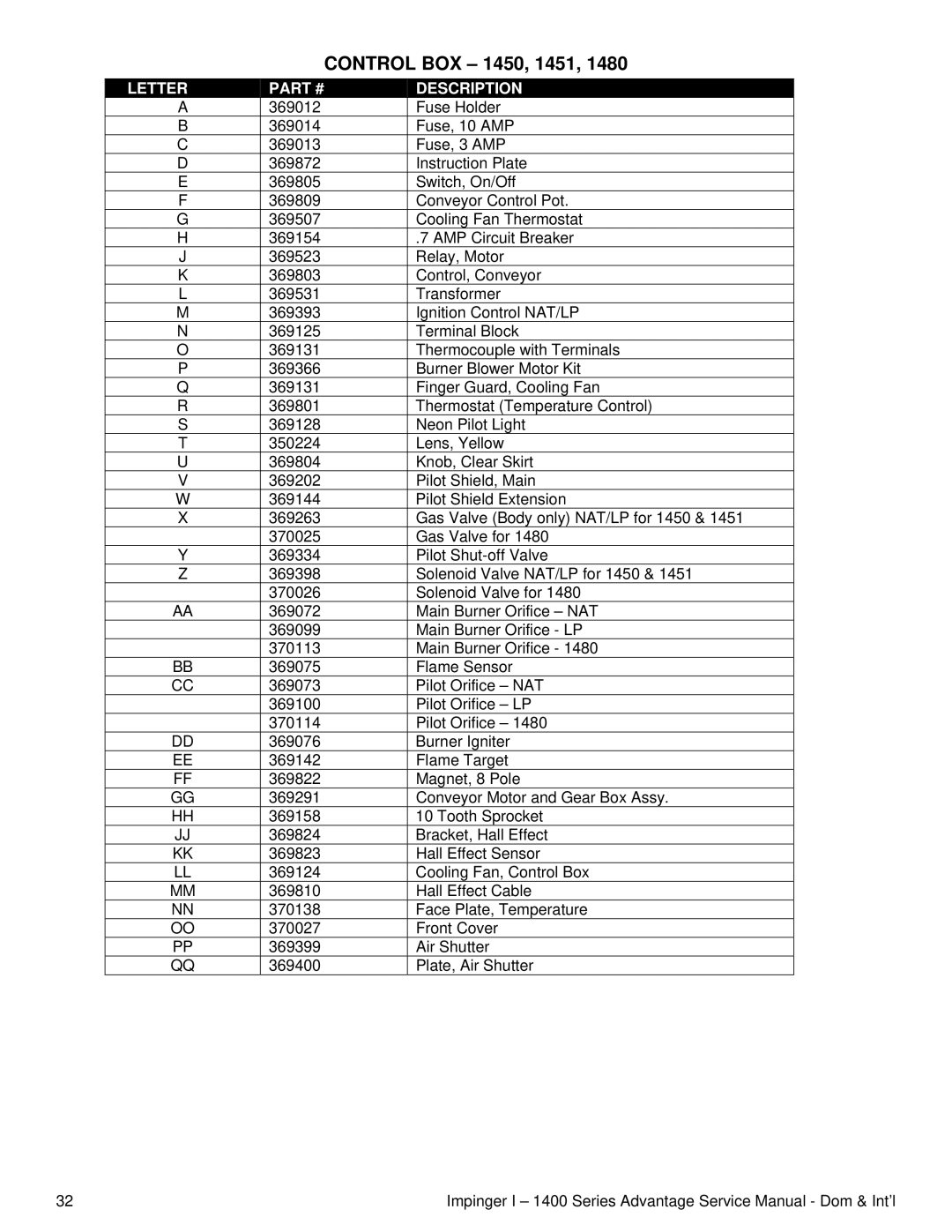
CONTROL BOX – 1450, 1451, 1480
LETTER | PART # | DESCRIPTION | |
A | 369012 | Fuse Holder | |
B | 369014 | Fuse, 10 AMP | |
C | 369013 | Fuse, 3 AMP | |
D | 369872 | Instruction Plate | |
E | 369805 | Switch, On/Off | |
F | 369809 | Conveyor Control Pot. | |
G | 369507 | Cooling Fan Thermostat | |
H | 369154 | .7 AMP Circuit Breaker | |
J | 369523 | Relay, Motor | |
K | 369803 | Control, Conveyor | |
L | 369531 | Transformer | |
M | 369393 | Ignition Control NAT/LP | |
N | 369125 | Terminal Block | |
O | 369131 | Thermocouple with Terminals | |
P | 369366 | Burner Blower Motor Kit | |
Q | 369131 | Finger Guard, Cooling Fan | |
R | 369801 | Thermostat (Temperature Control) | |
S | 369128 | Neon Pilot Light | |
T | 350224 | Lens, Yellow | |
U | 369804 | Knob, Clear Skirt | |
V | 369202 | Pilot Shield, Main | |
W | 369144 | Pilot Shield Extension | |
X | 369263 | Gas Valve (Body only) NAT/LP for 1450 & 1451 | |
| 370025 | Gas Valve for 1480 | |
Y | 369334 | Pilot | |
Z | 369398 | Solenoid Valve NAT/LP for 1450 & 1451 | |
| 370026 | Solenoid Valve for 1480 | |
AA | 369072 | Main Burner Orifice – NAT | |
| 369099 | Main Burner Orifice - LP | |
| 370113 | Main Burner Orifice - 1480 | |
BB | 369075 | Flame Sensor | |
CC | 369073 | Pilot Orifice – NAT | |
| 369100 | Pilot Orifice – LP | |
| 370114 | Pilot Orifice – 1480 | |
DD | 369076 | Burner Igniter | |
EE | 369142 | Flame Target | |
FF | 369822 | Magnet, 8 Pole | |
GG | 369291 | Conveyor Motor and Gear Box Assy. | |
HH | 369158 | 10 Tooth Sprocket | |
JJ | 369824 | Bracket, Hall Effect | |
KK | 369823 | Hall Effect Sensor | |
LL | 369124 | Cooling Fan, Control Box | |
MM | 369810 | Hall Effect Cable | |
NN | 370138 | Face Plate, Temperature | |
OO | 370027 | Front Cover | |
PP | 369399 | Air Shutter | |
369400 | Plate, Air Shutter |
32 | Impinger I – 1400 Series Advantage Service Manual - Dom & Int’l |