G-3 | | | | | | | | | | | | | | | | | | | | | | | | | | | ELECTRICAL DIAGRAMS | | | | | | | | | | | | | | | | | | | | | G-3 |
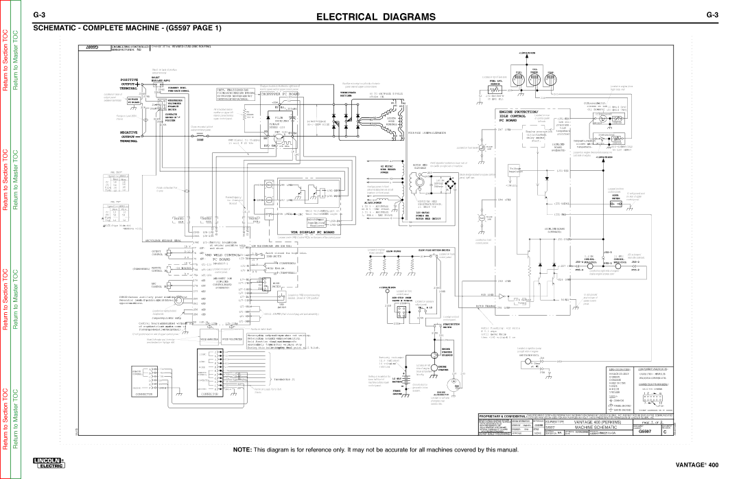
SCHEMATIC - COMPLETE MACHINE - (G5597 PAGE 1) | | | | | | | | | | | | | | | | | | | | | | | | | | | | | | | | | | | | | | | | | | | |
G5597 | ENGINEERING CONTROLLED CHANGE DETAIL: REVISED LEAD 208C ROUTING. | | | | | | | | | | | | | | | | | | | | | | | | | | | | | | | | | | | | | | | | | | | | |
MANUFACTURER: No | | | | | | | | | | | | | | | | | | | | | | | | | | | | | | | | | | | | | | | | | | | | | | | | | | | | | | |
| | | | | | | | | | | | | | | | | | | | | | | | | | | | | | | | | | | | | | +12VOLTS RUN | | | | | | | | | | | | | |
| | | | | | | | | | | | | | | | | | | | | | | | | | | | | | | | | | | | | | | | | | | | | | | | | | | | | | |
| | | | | | | | Shunt on back of positive | | | | | | | | | | | | | | | | | | | | | | | | | | | | | | | | | | | | OIL | | | | | | | | | | | | | |
| | | | | | | | output terminal | | | | | | | | | | | | | | | | | | | | | | | | | | | | | | | | | FUEL | | PRESS. | TEMP. | | | | | | | | | | | |
| | POSITIVE | | | | SHUNT | | | | | | | | | | | | | | | | | | | | | | | | | | | | | | | Located in top of fuel tank | 4 | 1 | 4 | 1 | 4 | 1 | | | | | | | | | | | |
| | | | | 50MV=400 AMPS | | | | | | | | | | | | | | | | | | | | | | | | | | | | | | | FUEL LVL. | | | | | | | | | | | |
| | | OUTPUT | | | | | | | | | | | | | | | | | Chopper module is located on right side of | | Rectifier is located on left side of interior | | | | | | | | | | SENSOR | | | | | | | | | | | | | Located in engine block | | |
| | TERMINAL | | | | | CURRENT LEVEL | | | | | | | | | | | panel behind upper control panel. | | | | | | | | | | | | | | | | | | | | | | | | | | |
| | | | | 204S | | | | | IGBT'S, FLYBACK DIODES AND | | interior panel behind upper control panel. | | | | | | | | | | | | | | | 229 | | | | | | | | | | | | Right side, rear | | | | |
| | | | | | | | FEED BACK SIGNAL | | | | | | | | | | | | | | | | | | | | | | | | | | | | | | | | | | | | | | | | |
Located on back of | 206B | | 206S | | | | | | | FILTER CAPACITORS ARE NTEGRALI | CHOPPPPER PC BOARD | | THREE PHASE | 60 TO | 65ACVPHASE | TO PHASE | | | | | | | | | | | | | 241 | | | | | | | | | | | |
| | | | | | | | | | | | | | 5J | 230 HMSO EMPTY | | | | | | | | | | | | | | | |
output panel | | | | | 206A | | | | | | | | TO CHOPPER MODULES AND NOT | | | | | | 13C | | | RECTIFIER | ATHIGH | IDLE | | | | | | | | | | | | 228 | | | | | | | | | | | | | |
| BY-PASS | | | | | WIREFEEDER | | | | | | INDIVIDUALLY REPLACEABLE. | | | | | | | | | | | | | | | | | | | 30 HMSO | FULL | | | | | | | | | | | | | | | | |
between terminals | | | | | | | | | | | | | | | | 13 | | | | | | | | | | | | | | | | | | | | | | | | | | | | | | | |
PC BOARD | | | | | | | | | | | | | | | | | | +COM | | | | | | | | W1 | W6 | | | | | | | | | | | | | | | | | OilPressureSwitch | | | | | | |
| | | | | | 21 | VOLTMETER | | | | | | | | | | | | | | | | | | | | | | | | | | | | | | | | | | | | | | | | | | | |
| | | | 208 | | POLARITY | | | | | | | | | | | | | | B2 | B5 | | | | | | | | W1 | W6 | | | | | | | | | | | | | | | | | | closes on low | 10 HMSO @ 0PSI | | | | |
| | | | 208A | | | | | | | | | | | | | | 7,200uFx6 | | | | | | | | | | | | | | | | | | | | | | | | | | |
| | | | | | | SWITCH | | | | | | R4 is located above | | R4 | | | | | | | | | | | | | | | | | | | | | ENGINE PROTECTION/ | | | | | | oil pressur. | 100 HMSO @ 75PS1 | | | |
| | | | | | | | | CONTACTS | | | | | | rectifier on upper left | | | | | | | | + | | | | | | | | | | | | | | | | | | | | | OILPRESSURE | | | | |
| Ferrite on Lead 208A | | | | | | | | | | interior panel behind | | 50OHM | | | | | | | | | | | | | | | | | | | | | IDLE CONTROL | | Located on rear | | | | | | | | |
| | | | 208C | SHOW N NI"+" | | | | | | | 100 W | | | | FILTER | | | | | W2 W2 | | STATOR | | | | | | | | | | of control panel | (J31-2346) | | | | | | | | | | |
| 2 turns | | | | | POSITION | | | | | | upper control panel. | | | | | | | | | | | | | | | | | | | | PC BOARD | | | | | | | | | | | | |
| | | | | | | | 208B | | | | | | | | | | | | | | CAPACITORS (6) | DC BUS VOLTAGE | W3 | | W ELD | | | | | | | | | | | left side. | Low oil | | | SWITCH | | | SENDER | | | | |
| | | | | | | | 206B | | | | | | | | | | | | | FLYBACK | | | 90+/-10VDC @ HIDLEI | | WINDINGS | | | | | | | | | | | | | | | pressureor | | | | | | | | |
| | | | | | | | | | Choke mounted behind | | | | | | | | | | W3 | | | | | | | | | | | | | | | | | | | | | | | | | |
| | | | | | | | | | | | | | | | | | | DIODES (12) | | | | | | | | | | | | | | | | 247 (J31-4) | | | | | | high | | | | | | | | | | |
| | NEGATIVE | | | | | | | | output terminal panel. | | | | | | | B3 | IGBT (16) B1 B4 | | | | | | | | | | | | | | | | | Engine protection | temperature | | | | | | | | | | |
| | | | | | | | | | | | | | | | | | | | | | | | FOUR POLE 1800RPM ALTERNATOR | | | | | | | | | | | | | | | | |
| | | | | | | | | | | | | | | | | | | | | | | | | | | | | | shutdown | | | | | | | | | | |
| | | OUTPUT | | | | | | | | | | | | | | | | | | | | C | E | | | | | | | W4 | W5 | | | | | | | | | | | circuitnute.1 mi | | | TEMPERATURE | | | | |
| | | | | | | | | | | CHOKE | | | PWM Signal to Chopper | B6 | | | | | | | | | | W4 | W5 | | | | | | | | | | | delay onngine | | | | | | | | | | | | | |
| | TERMINAL | | | | | | | | | | | | | | | | | | | | | | | | | | | | | | | | | | start. | | | | TemperaturewitchS | | | | | | | |
| | | | | | | | | | | | | | | | 15 | volt @ 20 kHz | | B7 | B8 | GATE SIGNAL | | | | | | | | | | | | | | | | | | | | | (SIMPLIFIED | | | closes | ongh hi SWITCH | | | SENDER | | | | |
| | | | | | | | | | | | | | | | | | | | | | | | | | | | | | | | | | ENG. | YELLOW | | | | | | | BOARD | | | temperature. | | | 500-600OHMS COLD | | |
| | | | | | | | | | | | | | | | | | | | | | | | | | | | | | | | | | | | | | Located on front panel PROT. | LAMP | | | | | | | | | | | | | 50-100 OHMS | OT | | | |
| | | | | | | | | | | | | | | | | | | | | | | | | 14 | | | | | | | | | | | | | | | | | | | | SCHEMATIC) | | | | | | | | |
| | | | | | | | | | | | | | | | | | | | | | | | | | | | | | | | | | | | | | | | | | | | | | | Located in engine thermostat housing on | | | | |
| | | | | | | | | | | | | | | | | | | | | | | | | | 14C | | | | | | | | | | | | | | | | | | | | | | | | | | |
| | | | | | | | | | | | | | | | | | | | | | | | | | | | | | | | | | | | | | | | | | | | | | | | Left side of engine | | | | | | | |
| | | | | | | | | | | | | | | | | | | | | | | | | | | | | | | | | | | | | | | | | | | | | | | | | | | +12VOLTS RUN | | | | |
| | | | | | | | | | | | | | | | | | | | | | | | | | | | | | | 41 | | | | Field capacitor located on lower rear of | | | | | | | | | | | | | | | | | | | |
| | | | | | | | | | | | | | | | | | | | | | | | | | | | | | | | | | ROTOR | FIELD | | | | | | | | | | | | | | | | | | | |
| | | | | | | | | | | | | | | | | | | | | | | | | | | | | | 42 OLTVAC | | fan baffle on right side of machine. | | Voltage | | | | | | | | | | | | | | | | |
| | | | | | | | | | | | | | | | | | | | | | | | | | | | | | WIRE | FEEDER | | SLIP RINGS | | | | | | | | | | (J31-2321) | | | | | | | | | | |
VRD OFF" | | | | | | | | | | | | | | | | | | | | | | | | | | | | | | | | | | | Regulator | | | | | | | | | | | | | |
| | | | | | | | | | | | | | | | | | | | | | | | | | POWER | | | | 200 | | | | | | | | | | | | | | | | | |
| | | | | | | | | | | | | | | | | | | | | | | | | | | | | | | | | | | | | | | | | | | | | | | |
| | | | | | | | | | | | | | | | | | | | | | | | | | | | | | | Diode Bridge located on upper control | | | | | | | | | | | | | | | | | | |
OpenCircuitVolts: | | | | | | | | | | | | | | | | | | | | | | | | | | | | | | | | 200A | | + | | | | | | | | | | | | | | | | | | |
| | | | | | | | | | | | | | | | | | | | | | | | | | | 42 | | | | panel, right rear. | | | | | | | | | | | | | | | | | | | |
| Max | | Min | | | | | | | | | | | | | | | | | | | | | | | | | | | | | | | | 160 DCV | | | | | | | | | | | | | | | | | | | |
CC | | | | | | | | | | | | | | | | | | | | | | | | | | | | | | | | | | | | | | | | | | | | | | | | | | | | | |
58 | | 58 | | | | | | | | | | | | | | | | | | | | | | | | | | | | 3 | | | | | | | | | | | | | | | | | | | | | | | | | | |
| | | | | | | | | | | | | | | | | 296 | | RED | | 299 (J61-4) | | | | | | | | | | 3200uf | | | | +10Volts | | | | | | | | | | | | | | | | |
CV | 58 | | 58 | | | | | | | | | | | | | | | | | | | | | Auxiliary power to front | | | | | | 300vdc | | | | | | | | | | | | | | | | | | | |
Pipe | 58 | | 26 | | | | | Ferrite onTwisted Pair | | | | | | | | | | | | | | | | | | -(J61-208B1) | | | | | | 5H | | | | | | | | | | | | | | | | Located on front | | | | |
Tig | 12 | | 12 | | | | | 4 turns | | | | | | | | | | | | | | | | | | | panel receptacles via circuit | | | | | 6A | | | | | | | | | | | | | | | | | | | |
| | | | | | | | | | | | | | | | | | | | | | | | | breakers on front panel. | | | | 201 | | | | | | | | | | | | | | | | | | | control panel. | 12 volt ground stud | | |
| | | | | | | | | | | | | | | | PowerSupply | | | | | | | | | | + | (J61-206B8) | 5 | | | | | | | | | | | | | | | | | | | | | | | | | HOUR | on rear of upper | | |
| | | | | | | | | | | | | | | | | | | | | | | | | | | | | | | | | | | | 244 (J33-1) | | | | | | | | | | | | | METER | | |
| | | | | | | | | | | | | | | | to Control | | | 296A | | GRN | | 297 (J61-9) | | | 4 | | | | | | | | | | | | | | | | | | | | | | | | control panel. | | |
VRD ON"" | | | | | | | | | | | | | | | | | | | | | | | | REVOLVING | FIELD | | | | | | | | | | | | | | | | + _ | | |
| | | | | | | | | | | | | Board | | | | | | | | | | | | AC AUX.POWER | | | | | | | | | | | | | (J31-)10263 | | | | | | | | | |
OpenCircuitVolts: | | | | | | | | | | | | | | | | | | | | | | | | | 5A | | RESISTANCE APPROX. | | | | | | | | | | | | | | | | | | |
| | | | | | | | | | | | | | | | | | | | | | | | | 3 TO 5 - AC1201PHASEV | | 25 | HMSO @ 75F | | | | | | | | | | | | | | | | | | | | | |
| Max | | Min | | | | | | | | | | | | | | 14 13 | | | | | | | | | Weld voltsRED>32,light on | 6A OT 5 -120VAC 1PHASE | | | | | | | | | | | | | | | | | | | | | | | | | | | |
CC | 12 | | 12 | | | | | | | | | | | | | | | | | | | | | | 3 TO 6 - AC2401PHASEV | | | 120 OLTVAC | | | | | | | | | | | | | | | | | | | | | | | |
| | | | | | | | | | | | | | | | | | 298 (J61-10) | +15DC | Weld voltsGREEN<32, light on | | | | | | | | | | | | | | (J31-2629) | | | | | | | | | | |
CV | 58 | | 58 | | | | | | | | | | | | | | | | | | | | 3, 4NDA 6 - | 240VAC 3PHASE | | POWER FOR | | | | | YELLOW | | | | | | | | | | | | | | | | |
Pipe | --- | | --- | | | | | | TWISTED | | | | TWISTED | | | | TWISTED | | | | | | | | | | | 6 | | ROTOR FIELD | CIRCUIT | | ALT. | | | | | | | | | | | | | | | | | | |
| | | | | | | | | | | | | | | | | | SwitchingPower | + (J60-14C6) | | | 6A | | LAMP | | | | | | | | | | | | | | | | | | |
*Tig | 12 | | 12 | | | | | | PAIR | | | | PAIR | | | | | PAIR | | | | | | | | | | | | | | | | | | | | | | | | | | | | | | | | | | | |
NOTE:Pipe Modes noti | | | | | | | | | | | -10) | | | | | | | | | | | | SupplyVoltageRegulator- (J60-13C) | | | | | 5H | | | | | | | | | | | | | | | | | | | | | | | | | |
* | | | VRDactiveOn | with | | | | | | | | 204S | | | 14(J3-16) | 13(J3-8) | | | | | | | VDR DISPLAY PC BOARD | | | | | | | | | | | | | | | | | (SIMPLIFIED BOARD | | | | | | | | | | | |
| | | | | | | | | | | | (J6-1) | | | | | | | | | | | | | | | | | | | | | | | | | | SCHEMATIC) | | | | | | | | | | | |
| | | | | | | | | | | | 206S | (J6-2)23(J3 25(J3-9) | | | | | | Located under VRD Control PCBd on the back of the control panel | | | | | | | | | | | | | | | | | | | | | | | | | | | | | | |
| | | | | | | | | | | | | | | | | | | | | | | | | | | | | | | | | Located on front | | | | | | | J31-232F)(2 | | | | | | | | | | |
| | | | | | | ARC VOLTAGE FEEDBACK SIGNAL | | | | | | | | | | | | | | | | | | | | | | | | | | | | | | | | | | | | | | | | | | | | | |
| | | | | | | | | 208C | (J3-15)Control boardmoncomis | | | | | | | | | | | | | | | | | | | | | | | | | | | | | | | | | | | | | | | |
| | | | | | | | | | | | | | | | | | | | | | | | | | | | | | | | | control panel. | | | | | | | | | | | | | | | | | | |
| | | | | | | | | | | V 77 | | at welder positiveut outp | | | | | | | | | | | | | | | | | | | | | | | | | | | | | | | | | | | | | | | | | |
| | | | | | | | | | 10 | (J71)- | and shunt | | (J2-5)405 LOW | IDLE COMM AND (0V @ LOW IDLE) | | | | Located in engine | GLOW PLUGS | GLOW PLUG BUTTON SWITCH | | | | | | | | | | | | | | | | | | | | | |
| | | | | | | | OUTPUT | | 0-10 V | | | | | | | | | | | | | | | | | | | | | | | | | | | | | | | J55-3 | | | | |
| | | | | | | | CONTROL 10K R1 | | | 76 | (J74)-VRD WELD CONTROL(J3-14)2570 V | | | Swich closed for high idle. | | intake manifold | | | | | | | Located on front | | | | | | | | | | | | | | J55 is located | | |
| | | | | | | | | | | | | | | | 239 | | | | | | | | | | | | | 0.2 HMO | | | 11 HMSO | | |
| | | | | | | | | | 0 V | | 75 | (J75)- | | PC BOARD | (J3-7)256 15 V | | IDLER SWITCH | | | | | | | | | | | control panel. | | | | | | | | | | | | | | | near idle solenoid. | | |
| | | | | | | | | | | | | | | | | | | | | | | | | | | | | | | | | | | | | | | | IDLE SOL. | | | IDLE SOL. | | |
| | | | | | | | | | 10 V | 77A | (J1-11) | P/N G5507-1 | (J1-4)2 | 15 V | | | 2A | (TOAMPHENOL) | | | | | | | | | | | | | | | | | | | | | 227 (B3) | | J55-4 PULLCOIL | P55-3HOLD COIL | | J55-2 | | |
| | | (TOAMPHENOL) | REMOTE | -15 VW/O(POT.) | | | | | | | | WELD TERM.SW. | | | | | | | | | | | | | | | | | | | | | | | | | | | | | | | |
| | | (J1-14)Located on back of | | | | | | | | | | | | | | | | | | | | | | | | | | | | | | P55-4 | | | | | | P55-2 | | |
| | | CONTROL 10K | | | 76A | (J1-3)4 0 V | | | | | | | | | | | | | | | | | | | | | | | | | | | | | | | Located on right side of engine | | | |
| | | | | | | | 0 V | | | | | control panel. | | | | 4A | (TOAMPHENOL) | | | | | | | | | | | | | | | | | | | | | | | | | | | | |
| | | | | | | | | | | 75A | (J1-10) | | | | | | | | | | | | | | | | | | | | | | | | | | | | | | | | | inside engine access door | | | | |
| | | | | | | | | | | | | | | | | | | | | | | | | | | | | | | | | | | | | | | | | | | | | | | | | | | | | | | |
| | | | | | | | | | | | 279 | -(J76) | | (SEE SHEET 2ORF | (J7-9)214 | | CV | | | | | | | | | | | | | | | | | | | | | 243 (J33-6) | | | | | | 226 (J31-8) | | | | | | | | | | |
| | | | | | | | | | | | | SIMPLIFIED | | PIPE | | | | | | | | | | | | | | | | | | | | | | | | | | | | | | | | | | | |
| | | | | | | | ARC | | | | | (J7-14)218 | | | MODE | | | | | | | | | | | | | | | | | | | | | | | | | | | | | | | | | |
| | | | | | | | | | | | | | CONTROLBOARD | CC | | | | | | | | | | | | | | | | | | | | | | | | | | | | | | | | | | | | |
| | | | | | | | CONTROL 10K R2 | | | 278 | -(J77) | | | | | | | SWITCH | | | | | | +12VOLTS RUN | | | | | | | | | | | | | | | | | | | | | | | | | | |
| | | | | | | | | | | SCHEMATIC) | (J7-15)220 | | TIG | | | | | | | | | | | | 238C | | | | | | | | | | | | | | | | | | | | | |
| | | | | | | | | | | | 277 | -(J78) | | | | | | | | | | | | | | | | | | | | | | | | | | | | | | | | | | | | |
| | | | | | | | | | | | | | | | | | | | | | | | | | | | Located on front | | | | 238B | | | | | | | | | | | | | | | | | | | | | |
| | | | | | | | | | | | | | | (J7-16)222 | | | | | | | | | | | | | | | | | | | | | | | | | | | | | | | | | | | | |
| | | | | | | | | | | | | | | | | | | | | | Located on VRD control mounting | | | | | control panel. | | | | | | 405 (J32-2) | | | | | | | | | | 12 volt ground | | | | | | | |
| | TOROID:Senses auxiliary power eloadi lerto.activat | | | | | | | (J7-2)215 | | | | | | | | | | | | | | | | | | | | | | | | | | | | | | | |
| | | 260 | -(J34) | | | | | | | | | | bracket. Shown in "ON" position | | | | | RUN-STOP SWITCH | | | | | | | | | 3/4 Second | | | 5S B1)( | | stud on rear of | | | | | | | |
| | Generator leaands 63 pasthroughtorroid3times in | | | | | | (J7-10)216 | | | | | | | | | | | | | | | | | | | | | | | | | | | |
| | | | | | | | | | | | | | | | | | | | | SHOWN NI RUNPOS. Located on auxiliary | | | | | | | | | upper control | | | | | | | |
| | oppositerectionsdi | . | | | | | | | 261 | -(J33) | | | | (J1-5)00 4 | | | | | VRD | | | | | | 232D | | 236B | output panel | | | | ROTOR FLASHING | | Timer | | | | | | | panel. | | | | | | | |
| | | | | | | | | | | | | | | | | | | | SWITCH | | | | | | | CB | A 10 | | | 200 (J33-5) | | | | | | | | | | | | | | | | | |
| | | | | | | | | | | | 250 | -(J35) | | | | | | | | | | | | | | | | | | | | | | | | | | | | | | | | | |
| | | | | | | | Located on wiring behind | | | | | | (J1-12)400 | | | | | | | | | | | | | | | | | | | | | | | | | | | | | | | | | | | | | | | | |
| | | | | | | | | | | | | | | | | | | | | | | | | | | | | | | | | | | | | | | | | | | | | | | | | | | | | | |
| | | | | | | | receptacles. | | | | 250 | -(J31) | | | | (J1-8)00 4 | | 400 I.D. JUMPER (Part of round plug and lead assembly.) | | | | | | | | | | Located on front | | | | | | | | | | | | | | | | | | | | |
| | | | | | | | Jumperequiredfor outp. | | | | | | | | | | | | | | | | | | | | | | 236A | | | | | | | | | | | | | | | | | | | | | |
| | | | | | | | | | | | | | | | | | | | | | | | | | | | | | | | | control panel. | | | | | | | | | | | | | | | | | | | | |
| | | | | | | | | | | | 5G | (J2-3) | | | | (J1-13)400 | | | | | | | | | | | | | | | | | | | | | | | | | | | | | | | | | | | | | | |
| | | | Control | board associatedcirui withpartJ2 | | | | | | | | | | | | | | | | | | 232H | | | | STARTBUTTON | | | | | | | | | | | | | | | | | | | |
| | | | are | (J4-110)to | (J5-110)to | | | | | | | | | | | | | | | | | | | | | | | | | | | | | | | | | | | | |
| | | | of | engineelctricalem systandrea common to | | | | | | | | | | | | | | | | | | | | | | | | | | | SWITCH | | Rotor Flashing: +12 volts | | | | | | | | | | | | | | | | |
| | | | frameroundg negative( atteryb rminal)te . | | | | | | | | | Ferrite on meter leads | | | | | | | | | | | | | | | | | | | | | | | | | | | | | | | |
| | | | | | | | | | | | | | | | | | | | | | | | | | | | | | | | | | | | | | | | | | | |
| | | | | | | | | | | | | | | | | | | | | | | | | | | | @ 0.5 amps | | | | | | | | | | | | | | | | | | |
| | | | | | | | | | | | | | | | | | | | | | | | | | | | | | | | | | | | 238A | | | | | | | | | | | | | | | | | | | |
| | | 12 volt ground stud on rear of upper control panel. | | | | | | | | | | | | | | | | | | | | | | | | | | | | until ratorgene dsbuilup | | | | | | | | | | | | | | | | | |
| | | | | | | | | | | Meters playdis | | setpoinvoltsmpsor whena | not welding. | | | | | | | | | | 231 | | | | | | | | | | | | | | | | | | |
| | | | | | | | | | | | | | | | | | | | | | | | | | | | | then +160 voltsps@. 0 am | | | | | | | | | | | | | | | | |
| | | | | | | Weld Voltmeter and Ammeter | | | | WELD AMMETER W ELD VOLTMETER | Meters playdis | | actualolts vandmpsawhenwelding. | | | | | | | | | | | 238 | | | | | | | | | | | | | | | | | |
| | | | | | | | | | | | | | | | | | | | | | | | | | | | | | | | | | | | | | | | | |
| | | | | | | | | | Hold function displaysualvoltsdactampsan rfo | | | | | | | | | | | | | | | | | | | | | | | | | | | | | | | |
| | | | | | | are standard on Vantage 400 | | | | | | | | | | | | | | | | | | | | | | | | | | | | | | | | | | | | | | | | |
| | | | | | | | | | | | | | | approximately | 5 ndssecoafter weldings. stop | | | | | | | | | | | | | | | | | | | | | | | | | | | | | | | | |
| | | | | | | | | | | | | | | | | | | | | | | | | | | | | | | | | | | | | | | | | | | | | | | | | |
| | | | | | | | | | | | | | | | | | During | this | holdhedisplayrightmost decimalt | point | will blink. | | | | | | | | | | ENGINE | | | | | Located in injection pump | | | | | | | | | | | | | |
| | | | | | | | | | | | | | | | | | | | | | | | | | | | | | | | | | | | | | | | | | | | | | | | | | | | | |
| | | | | | | | | | | | 115VAC | | J | 31 | | | | | | | | | | | | | | | | | | | | | STARTER | | | | | on right side of engine | | | | | | | | | | | | | |
| | | | | | | | | | | | | A | 32 | | | | | | | | | | | | | | Battery voltage: | | | | SOLENOID | | | | SHUTDOW N COIL | | | | | | | | | | | | | |
| | | | | | | | | | | | | | | | | | | | | | | | | | | | | | | | | | | | | | | J56 | | | | | | | | | | | | | |
| | | | | | | | | | | | | | | I | 41A | | | | | | | | | | | | | | | | | | | | | | | | | | | | | | | | | | | | | |
| | | | | | | | | | | | | 42VAC | | | | | | | | | | | | | | | 12.6 | voltsatrest | | | | | | | | | | | | | | 262 | | | | | | | | | | | |
| | | | | | | | | | | | | | K | 42A | | | | | | | | | | | | | | 14 voltsgineen | | | | | | | | | | | | 9 Ohms | | | | | | | | | | | | |
| | | | | | | | | | | | | | | | | | | | | | | | | | | | | Located on left | | | | | | | | | | | | | | | | | | | | | |
| | | | | | | | | | | | W ORK | | H | 21 | | | | | | | | | | | | | | running | | | | ENGINE | | | | | | | at 75vF | | | | | | | | | | | | | |
| | | | | | | A | 77B | | | | | | | | | | | | | | | | | | | | side of engine | | | | | | | | | | | | | | | | LEAD COLOR CODE: | COMPONENTVALUE UNITS: | |
| | | | | | | | | | | | | E | 77A | | | | | | | | | | | | | | | | | | | STARTER | | | | | | | | | | | | | | | | | |
| | | REMOTE | | | | | | | | | | | | | | | | | | | | | | | | | | block at flywheel | | | | | | | | P56 | 5P | | | | | | | | |
| | | | | | 76B | | | | REMOTE | | | | | | | | | | | | | | | | | | + | | | | | | | | | | | | | | | | | | | | |
| | | CONTROL | | B | | | | | F | 77B | | | | | | | | | | | | | | | | housing. | | | 238 | 243 | | | | | | | | | | | | | B-BLACK OR GRAY | CAPACITOR: MFD/VOLTS | |
| | | | | | | | CONTROL | | 76A | | | | | | | | | | | | | | | | | | | | | | | | | | | | | | | | | |
| | | | | | | C | 75B | | | | | | | G | 76B | | | | | | | | | | | | Battery is located in the | 12 OLTV | | | | | | | | | | | | | | | | | | | | | G-GREEN | | RESISTOR:OHMS/WATTS | |
| | | | | | | | 2B | | | | CONTACTOR | | 75A | | | | | | | TOCONNECTOR J1 | | | lower left front of | | | | | | | | | | | | | | | | | | | | | | O-ORANGE | | |
| | | | | | | D | | | | | D | 75B | | | | | | | | | BATTERY | | | | | + | | | | | | | | | | | | | | | | | | | |
| | | | | | | 4B | | | | | | | 4A | 4B | | | | | | | | | | | | machine behind lower | | | | | | | | | | | | | | | | | | | | R-RED OR PINK | | CONNECTOR PIN NUMBERS: | |
| | | | | | | E | | | | | | | C | 2A | | | | | | | | | | | | | | Ground stud on | | | | | | | | | | | | | | | | | | | | |
| | | | | | | | | | | | | | | | | | | | | | | | control panel. | | | | | | D+ | | | | | | | | | | | | | | | | U-BLUE | | |
| | | GROUND | | | F | GND-B | | | | | | 2B | | | | | | | | | | | | | | | generator cross | | | | | | | | | | | | | | | | | | | | | |
| | | | | | | GROUND | | B | GND-A | | Ferrite on Leads 75A & 76A | | | | | | | | | | | | | | | | | | | | | | | | | | | | W-WHITE | | EX.12 PIN | CONNECTOR | |
| | | | | | | | | | | | | | | | | | | | | FRAME | support. | | | | | | | | | | | | | | | | | | | | | |
| | | | CONNECTOR | | | | | CONNECTOR | | | | 3 turns | | | | | | | | | | | | | | ENGINE | | | | | | | | | | | | | | | | | Y-YELLOW | | 1 2 | 6 | |
| | | | | | | | | | | | | | | | | | | | | | GROUND | | | | | | | | | | | | | | | | | | | | | |
| | | | | | | | | | | | | | | | | | | | | | | | | | | ALTERNATOR | | | | | | | | | | | | | | | | | LABELS: | | |
| | | | | | | | | | | | | | | | | | | | | | | | | | | | | | | | | | | | Located on left side | | | | | | | | | | | | | | | | | | | | |
| | | | | | | | | | | | | | | | | | | | | | | | | | | | | | | | | | | | | | | | | | | | | | | | | | | | COMM ON | | | | |
| | | | | | | | | | | | | | | | | | | | | | | | | | | | | | | | | | | | of engine near | | | | | | | | | | | | | | | | | | 7 | 12 | |
| | | | | | | | | | | | | | | | | | | | | | | | | | | | | | | | | | | | radiator fan. | | | | | | | | | | | | | | | | | FRAME GROUND | |
| | | | | | | | | | | | | | | | | | | | | | | | | | | | | | | | | | | | | | | | | | | | | | | | | | | | | LATCH | |
| | | | | | | | | | | | | | | | | | | | | | | | | | | | | | | | | | | | | | | | | | | | | | | | | | | | | | | |
| | | | | | | | | | | | | | | | | | | | | | | | | | | | | | | | | | | | | | | | | | | | | | | | | | | | | | EARTH GROUND | VIEWOF CONNECTOR ON PC BOARD | |
| | | | | | | | | | | | | | | | | | | | | | | | | | | | | | | | | | | | | | | PROPRIETARY & CONFIDENTIAL:THIS DOCUMENT CONTAINS PROPRIETARY INFORMATION OWNED BY LINCOLN GLOBAL, INC. AND MAY NOT BE DUPLICATED, COMMUNICATED | |
| | | | | | | | | | | | | | | | | | | | | | | | | | | | | | | | | | | | | | | | | | | | TO OTHER PARTIES OR USED FOR ANY PURPOSE WITHOUT THE EXPRESS WRITTEN PERMISSION OF LINCOLN GLOBAL, INC. | |
| | | | | | | | | | | | | | | | | | | | | | | | | | | | | | | | | | | | | | | MANUFACTURING TOLERANCE PER E2056 | DESIGN INFORMATION | REFERENCE: | EQUIPMENT TYPE: | | VANTAGE 400 (PERKINS) | | 1 | 2 | |
| | | | | | | | | | | | | | | | | | | | | | | | | | | | | | | | | | | | | | | UNLESS OTHERWISE SPECIFIED TOLERANCE: | | | |
| | | | | | | | | | | | | | | | | | | | | | | | | | | | | | | | | | | | | | | ON 2 PLACE DECIMALS IS ± .02 | DRAWN BY: | Maglietta | G5388 | | | | | PAGE ___ OF ___ | SOLIDEDGE |
| | | | | | | | | | | | | | | | | | | | | | | | | | | | | | | | | | | | | | | ON 3 PLACE DECIMALS IS ± .002 | SUBJECT: | | | MACHINE SCHEMATIC | | DOCUMENT | DOCUMENT |
EN-170 | | | | | | | | | | | | | | | | | | | | | | | | | | | | | | | | | | | | | | | ON ALL ANGLES IS ± .5 OF A DEGREE | ENGINEER: | BAM | SCALE: | | | | NUMBER: | REVISION: |
| | | | | | | | | | | | | | | | | | | | | | | | | | | | | | | | | | | | | | MATERIAL TOLERANCE ("t") TO AGREE | | | |
| | | | | | | | | | | | | | | | | | | | | | | | | | | | | | | | | | | | | | | | | | | | | | | | G5597 | C |
| | | | | | | | | | | | | | | | | | | | | | | | | | | | | | | | | | | | | | WITH PUBLISHED STANDARDS. | | | | | MATERIAL | | APPROVAL | | PROJECT | | | | |
| | | | | | | | | | | | | | | | | | | | | | | | | | | | | | | | | | | | | | DO NOT SCALE THIS DRAWING | APPROVED: | | NONE | DISPOSITION: NA | DATE: | | 10/26/2006 NUMBER:CRM22115-GA | |