TOC

G-14

ELECTRICAL DIAGRAMS

G-14

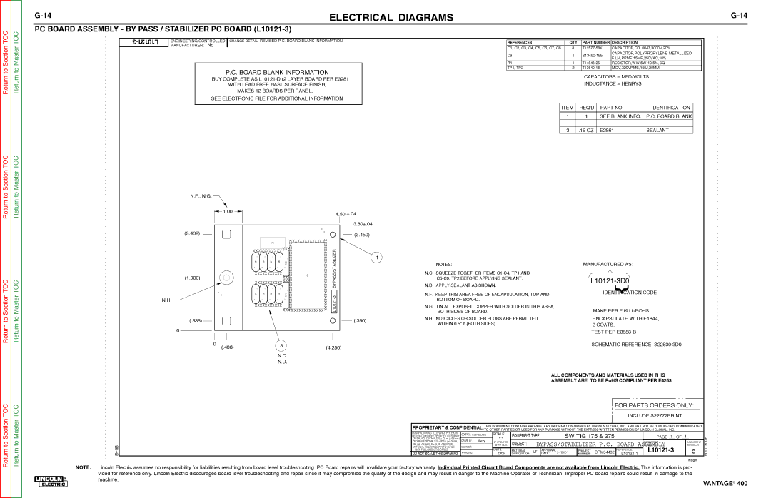
PC BOARD ASSEMBLY - BY PASS / STABILIZER PC BOARD (L10121-3)


Return to Section

Return to Master

3-L10121

ENGINEERING CONTROLLED CHANGE DETAIL: REVISED P.C. BOARD BLANK INFORMATION

MANUFACTURER: No

P.C. BOARD BLANK INFORMATION

BUY COMPLETE AS L10121-D (2 LAYER BOARD PER E3281

WITH LEAD FREE HASL SURFACE FINISH). MAKES 12 BOARDS PER PANEL.

SEE ELECTRONIC FILE FOR ADDITIONAL INFORMATION

REFERENCES

QTY

PART NUMBER

DESCRIPTION


C1, C2, C3, C4, C5, C6, C7, C8

8

T11577-58K

CAPACITOR,CD,.0047,3000V,20%


C9

1

S13490-155

CAPACITOR,POLYPROPYLENE METALLIZED

FILM,PPMF,15MF,250VAC,10%


R1

1

T14648-25

RESISTOR,WW,5W,10,5%,SQ

TP1, TP2

2

T13640-18

MOV,320VRMS,150J,20MM

CAPACITORS = MFD/VOLTS

INDUCTANCE = HENRYS

ITEM

REQ'D

PART NO.

IDENTIFICATION


1

1

SEE BLANK INFO.

P.C. BOARD BLANK


3

.16 OZ

E2861

SEALANT

Return to Section TOC

Return to Section TOC

Return to Section TOC

Return to Master TOC

Return to Master TOC

Return to Master TOC

N.F., N.G.


1.00


4.50 ±.04


3.80±.04


(3.462)


(3.450)


XXXTP1

XXXXXXXXXXXXXC9

XXXXXXXXXXXXXXXXXXXXXXXXXXXXX

BYPASS/STABILIZER3-L10121


R1


XXXXXXXXXXXXXXXXXXXXXXXXXXXXX


XXXXXXXXXXXXX


1


C5

C6

C7

C8

TP2


NOTES:

MANUFACTURED AS:

(1.900)

XXXXXXXXXXX


N.C. SQUEEZE TOGETHER ITEMS C1-C4, TP1 AND


XXX


C5-C9, TP2 BEFORE APPLYING SEALANT.

L10121-3D0


XXXXXXXXXXX XXX


N.D. APPLY SEALANT AS SHOWN.


C1

C2

C3

C4


N.F. KEEP THIS AREA FREE OF ENCAPSULATION, TOP AND

IDE

ATION CODE


N.H.


BOTTOM OF BOARD.


XXXXXXXXXXX


N.G. TIN ALL EXPOSED COPPER WITH SOLDER IN THIS AREA,


BOTH SIDES OF BOARD.

MAKE PER E1911-ROHS

(.338)


(.350)

N.H. NO ICICLES OR SOLDER BLOBS ARE PERMITTED

ENCAPSULATE WITH E1844,


WITHIN 0.5" 0 (BOTH SIDES).

2 COATS.


0


TEST PER E3553-B


0

(.438)


3


(4.250)


SCHEMATIC REFERENCE: S22530-3D0


N.C.,


N.D.


ALL COMPONENTS AND MATERIALS USED IN THIS


ASSEMBLY ARE TO BE RoHS COMPLIANT PER E4253.


FOR PARTS ORDERS ONLY:


INCLUDE S22772PRINT


PROPRIETARY & CONFIDENTIAL:THIS DOCUMENT CONTAINS PROPRIETARY INFORMATION OWNED BY LINCOLN GLOBAL, INC. AND MAY NOT BE DUPLICATED, COMMUNICATED


TO OTHER PARTIES OR USED FOR ANY PURPOSE WITHOUT THE EXPRESS WRITTEN PERMISSION OF LINCOLN GLOBAL, INC.


MANUFACTURING TOLERANCE PER E2056

CONTROL: CLEVELAND

SCALE:

EQUIPMENT TYPE:


SW TIG 175 & 275


1


1


UNLESS OTHERWISE SPECIFIED TOLERANCE:


ON 2 PLACE DECIMALS IS ± .02 in. (± 0.5 mm)


1:1


PAGE ___ OF ___

SOLIDEDGE


DRAWN BY:

fivory


ON 3 PLACE DECIMALS IS ± .002 in. (± 0.05 mm)

IF PRINTED

SUBJECT:

BYPASS/STABILIZER P.C. BOARD

DOCUMENT


DOCUMENT


@ A2 SIZE

NUMBER:


REVISION:

EN-168

ON ALL ANGLES IS ± .5 OF A DEGREE


-


MATERIAL TOLERANCE ("t") TO AGREE

ENGINEER:


L10121-3


C

DO NOT SCALE THIS DRAWING

APPROVED:

-

INCH

DISPOSITION: UF

DATE:

9-72007-

NUMBER: CRM34432


L10121-1


WITH PUBLISHED STANDARDS.


UNITS:

MATERIAL


APPROVAL


PROJECT


REFERENCE:


Insight

NOTE: Lincoln Electric assumes no responsibility for liablilities resulting from board level troubleshooting. PC Board repairs will invalidate your factory warranty. Individual Printed Circuit Board Components are not available from Lincoln Electric. This information is pro- vided for reference only. Lincoln Electric discourages board level troubleshooting and repair since it may compromise the quality of the design and may result in danger to the Machine Operator or Technician. Improper PC board repairs could result in damage to the

®machine.

VANTAGE® 400

Page 166
Image 166
Lincoln Electric 400 service manual PC Board Assembly by Pass / Stabilizer PC Board L10121-3

400 specifications

The Lincoln Electric 400 is a state-of-the-art multi-process welding machine designed to meet the demands of today’s industrial welding applications. Renowned for its reliability and versatility, this welder is a preferred choice among professionals in fabrication, construction, and maintenance industries.

One of the main features of the Lincoln Electric 400 is its multi-process capability. It seamlessly integrates MIG, TIG, and stick welding processes into a single unit, allowing users to switch between methods depending on the job at hand. This flexibility makes it incredibly suitable for a wide range of materials, including steel, stainless steel, and aluminum.

The welding machine boasts a robust power output, with a maximum range of 400 amps. This impressive capacity enables it to handle thick materials effectively, making it ideal for heavy-duty tasks. The machine operates on both single-phase and three-phase power, giving users the advantage of versatility depending on the power source available at the job site.

Another significant characteristic of the Lincoln Electric 400 is its advanced digital display and control interface. This user-friendly panel allows for easy adjustments to voltage and wire feed speed, ensuring precision and high-quality welds. Additionally, the machine includes built-in features to improve the consistency of welding, such as the Smart MIG technology which optimizes the welding parameters automatically based on the wire diameter and material thickness.

In terms of durability, the Lincoln Electric 400 is designed for rugged environments. Its heavy-duty construction, including a robust metal casing and protective features, ensures it can withstand the rigors of daily use in harsh conditions. Furthermore, the welder is often praised for its efficient cooling system, which prolongs the machine's lifespan and maintains optimal performance even during extended usage.

Portability is another key aspect of this welding machine. Weighing under 200 pounds, it is designed with mobility in mind. The integrated wheels allow for easy transportation between job sites, making it a practical choice for mobile welders and contractors.

In conclusion, the Lincoln Electric 400 stands out in the welding equipment market due to its multi-process capabilities, impressive power output, user-friendly interface, durability, and portability. It is engineered to exceed the expectations of professional welders, providing them with the tools needed for high-quality results across a variety of applications.