4.16 Cover assembly and Base assembly | 4 Replacement Procedures |
3.Turn over the computer and open the display.
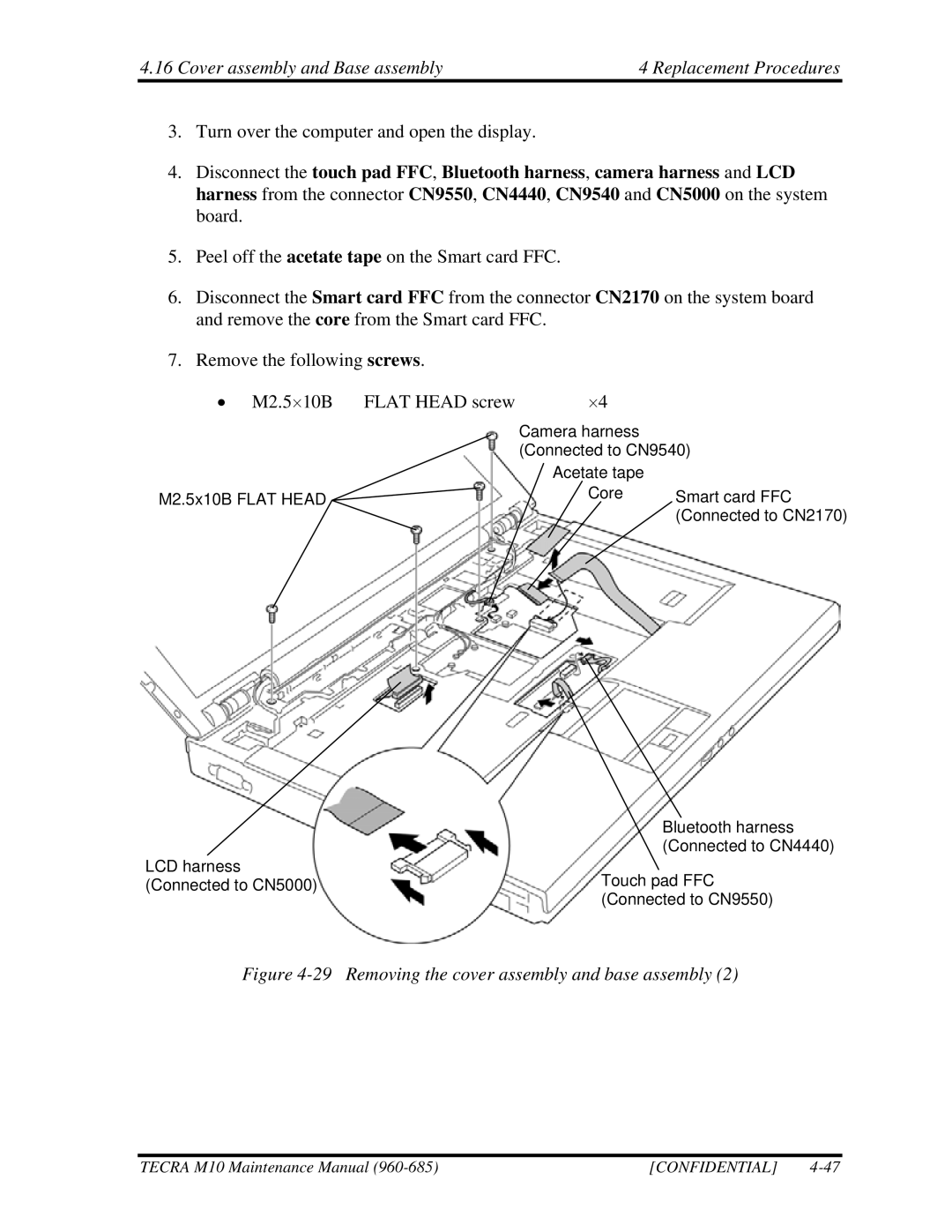
4.Disconnect the touch pad FFC, Bluetooth harness, camera harness and LCD harness from the connector CN9550, CN4440, CN9540 and CN5000 on the system board.
5.Peel off the acetate tape on the Smart card FFC.
6.Disconnect the Smart card FFC from the connector CN2170 on the system board and remove the core from the Smart card FFC.
7.Remove the following screws.
• M2.5⋅10B FLAT HEAD screw | ⋅4 |
|
| Camera harness |
|
| (Connected to CN9540) | |
| Acetate tape |
|
M2.5x10B FLAT HEAD | Core | Smart card FFC |
|
| (Connected to CN2170) |
Bluetooth harness (Connected to CN4440)
LCD harness
(Connected to CN5000)Touch pad FFC (Connected to CN9550)
Figure 4-29 Removing the cover assembly and base assembly (2)
TECRA M10 Maintenance Manual | [CONFIDENTIAL] |