4 Replacement Procedures | 4.16 Cover assembly and Base assembly |
4.16 Cover assembly and Base assembly
Removing the Cover assembly and Base assembly
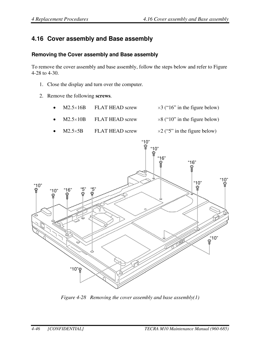
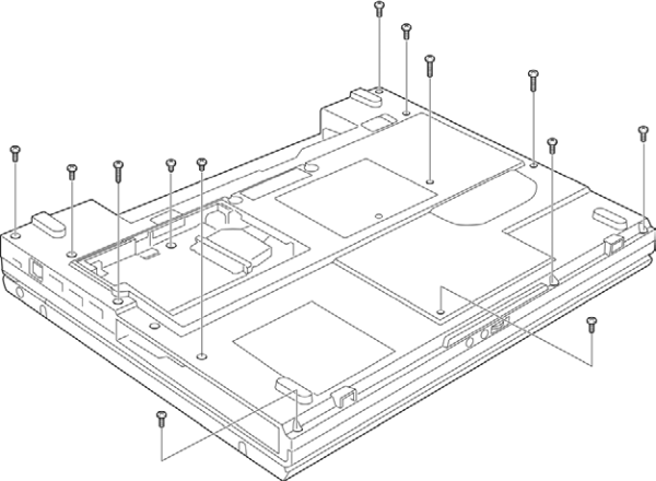
To remove the cover assembly and base assembly, follow the steps below and refer to Figure
1.Close the display and turn over the computer.
2.Remove the following screws.
• | M2.5⋅16B | FLAT HEAD screw | ⋅3 (“16” in the figure below) |
|
• | M2.5⋅10B | FLAT HEAD screw | ⋅8 (“10” in the figure below) |
|
• | M2.5⋅5B | FLAT HEAD screw | ⋅2 (“5” in the figure below) |
|
|
|
| “10” |
|
|
|
| “10” |
|
|
|
| “16” |
|
|
|
| “16” |
|
“10” |
|
| “10” | “10” |
|
|
| ||
“16” “5” | “5” |
|
| |
“10” |
|
|
“10”
“10”
Figure 4-28 Removing the cover assembly and base assembly(1)
| TECRA M10 Maintenance Manual |