4 Replacement Procedures | 4.8 Optical disk drive | |||
3. | Remove the following screws and ODD rear bracket. | |||
| • | M2.0⋅2.7C | Unique screw | ⋅2 |
4. | Remove the following screw and ODD side bracket. | |||
| • | M2.0⋅3C | ⋅1 | |
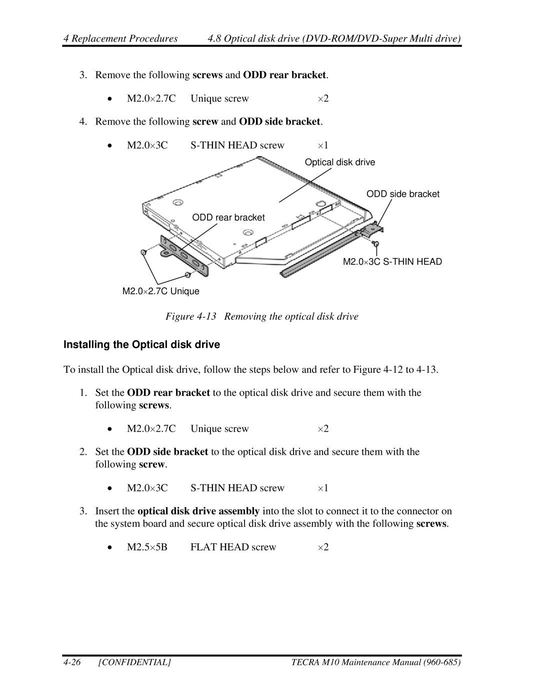
Optical disk drive
ODD side bracket
ODD rear bracket
M2.0⋅3C
M2.0⋅2.7C Unique
Figure 4-13 Removing the optical disk drive
Installing the Optical disk drive
To install the Optical disk drive, follow the steps below and refer to Figure
1.Set the ODD rear bracket to the optical disk drive and secure them with the following screws.
• M2.0⋅2.7C Unique screw | ⋅2 |
2.Set the ODD side bracket to the optical disk drive and secure them with the following screw.
• M2.0⋅3C | ⋅1 |
3.Insert the optical disk drive assembly into the slot to connect it to the connector on the system board and secure optical disk drive assembly with the following screws.
• M2.5⋅5B | FLAT HEAD screw | ⋅2 |
[CONFIDENTIAL] | TECRA M10 Maintenance Manual |