4 Replacement Procedures | 4.27 Touch pad/Fingerprint sensor board |
Installing the Touch pad/Fingerprint sensor board
To install the touch pad/fingerprint sensor board, follow the steps below and refer to Figure
1.Connect the touch pad button FFC to the connector on a new touch pad and stick the touch pad in place.
2.Set the fingerprint sensor board to the unit dual pad and secure them with the following screws.
• M2.0⋅3C | ⋅2 |
3.Set the unit dual pad (with the fingerprint sensor board) in place.
4.Connect the touch pad FFC, touch pad button FFC and dual button FFC to the connector CN9650 and CN3240 on the fingerprint sensor board and connector on the touch pad.
5.Turn up the insulator (TPAD PLT INSULATOR) and secure the touch pad plate (with the fingerprint sensor board) with the following screws.
• M2.5⋅4B | FLAT HEAD screw | ⋅4 |
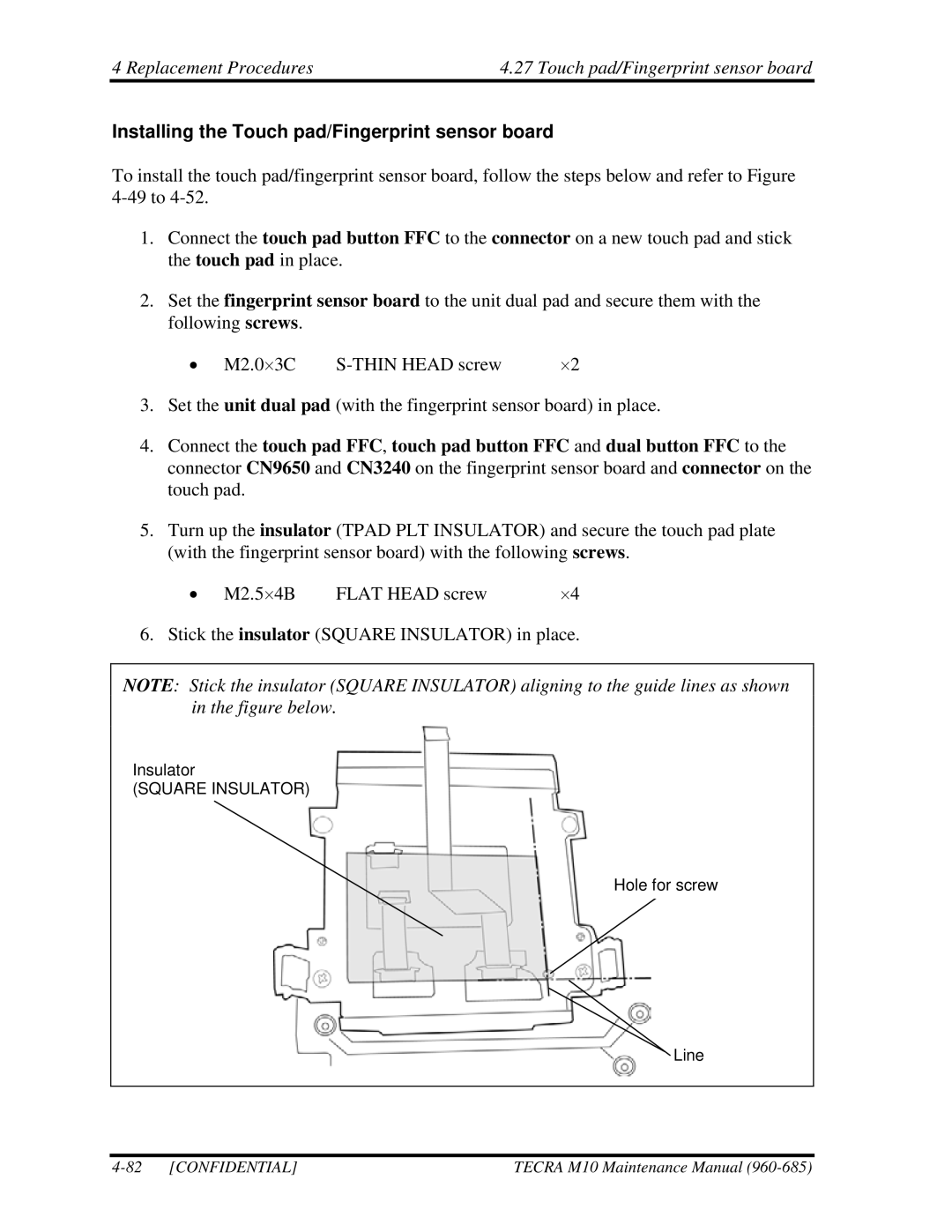
6. Stick the insulator (SQUARE INSULATOR) in place.
NOTE: Stick the insulator (SQUARE INSULATOR) aligning to the guide lines as shown in the figure below.
Insulator
(SQUARE INSULATOR)
Hole for screw
Line
| TECRA M10 Maintenance Manual |
