TROUBLESHOOTING | ||
|
|
|
| Observe all Safety Guidelines detailed throughout this manual |
|
|
|
|
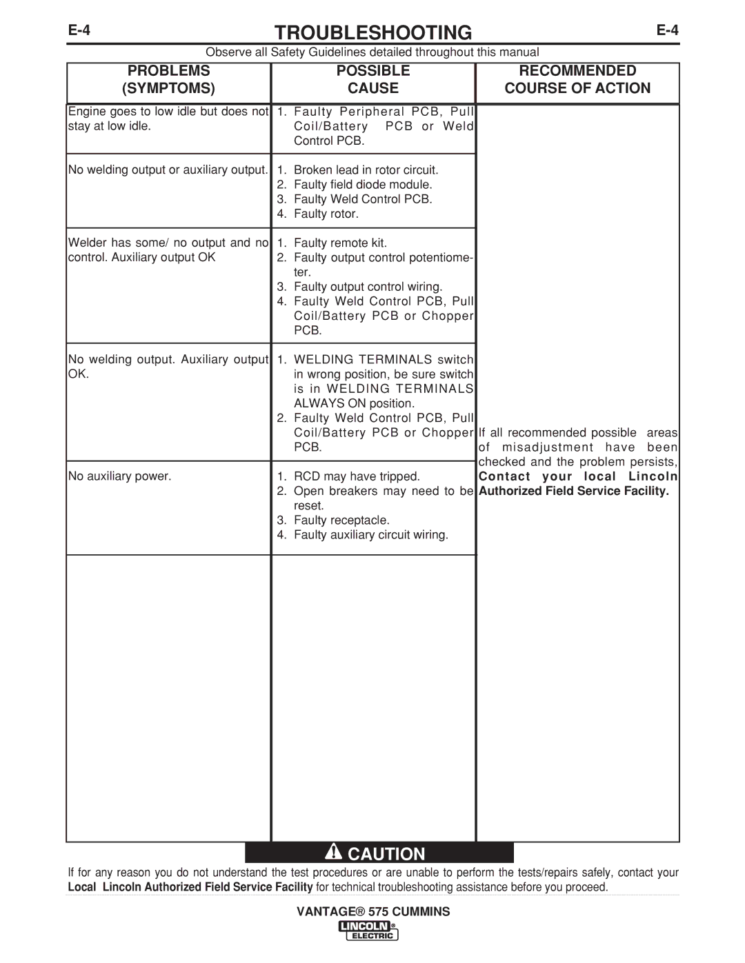
PROBLEMS
(SYMPTOMS)
POSSIBLE
CAUSE
RECOMMENDED
COURSE OF ACTION
Engine goes to low idle but does not | 1. Faulty Peripheral PCB, | Pull |
| ||
stay at low idle. |
| Coil/Battery PCB or | Weld |
| |
|
| Control PCB. |
|
|
|
|
|
|
| ||
No welding output or auxiliary output. 1. Broken lead in rotor circuit. |
|
|
| ||
| 2. | Faulty field diode module. |
|
|
|
| 3. | Faulty Weld Control PCB. |
|
|
|
| 4. | Faulty rotor. |
|
|
|
|
|
|
|
|
|
Welder has some/ no output and no | 1. | Faulty remote kit. |
|
|
|
control. Auxiliary output OK | 2. | Faulty output control potentiome- |
| ||
|
| ter. |
|
|
|
| 3. | Faulty output control wiring. |
|
|
|
| 4. | Faulty Weld Control PCB, Pull |
| ||
|
| Coil/Battery PCB or Chopper |
| ||
|
| PCB. |
|
|
|
|
|
|
| ||
No welding output. Auxiliary output | 1. WELDING TERMINALS switch |
| |||
OK. |
| in wrong position, be sure switch |
| ||
|
| is in WELDING TERMINALS |
| ||
|
| ALWAYS ON position. |
|
|
|
| 2. | Faulty Weld Control PCB, Pull |
| ||
|
| Coil/Battery PCB or Chopper If all recommended possible | areas | ||
|
| PCB. |
| of misadjustment have | been |
|
|
|
| checked and the problem persists, | |
|
|
|
| ||
No auxiliary power. | 1. | RCD may have tripped. |
| Contact your local Lincoln | |
| 2. | Open breakers may need to be Authorized Field Service Facility. | |||
|
| reset. |
|
|
|
| 3. | Faulty receptacle. |
|
|
|
| 4. | Faulty auxiliary circuit wiring. |
| ||
![]() CAUTION
CAUTION
If for any reason you do not understand the test procedures or are unable to perform the tests/repairs safely, contact your Local Lincoln Authorized Field Service Facility for technical troubleshooting assistance before you proceed.
VANTAGE® 575 CUMMINS
