OPERATION | ||
|
|
|
(See Customer Assistance Policy in the front of this Instruction Manual)
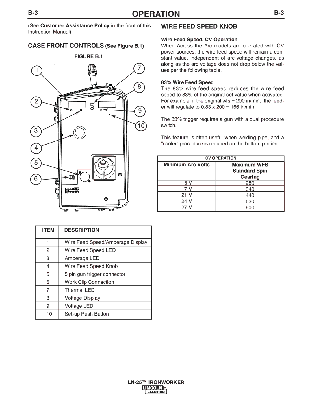
CASE FRONT CONTROLS (See Figure B.1)
| FIGURE B.1 |
1 | 7 |
|
8
2
9
![]()
![]()
![]() 10 3
10 3 ![]()
![]()
![]()
![]()
![]()
![]()
4
5
6
ITEM | DESCRIPTION |
|
|
1 | Wire Feed Speed/Amperage Display |
|
|
2 | Wire Feed Speed LED |
|
|
3 | Amperage LED |
|
|
4 | Wire Feed Speed Knob |
|
|
5 | 5 pin gun trigger connector |
|
|
6 | Work Clip Connection |
7 | Thermal LED |
|
|
8 | Voltage Display |
|
|
9 | Voltage LED |
|
|
10 | |
|
|
WIRE FEED SPEED KNOB
Wire Feed Speed, CV Operation
When Across the Arc models are operated with CV power sources, the wire feed speed will remain a con- stant value, independent of arc voltage changes, as along as the arc voltage does not drop below the val- ues per the following table.
83% Wire Feed Speed
The 83% wire feed speed reduces the wire feed speed to 83% of the original set value when activated. For example, if the original wfs = 200 in/min, the feed- er will regulate to 0.83 x 200 = 166 in/min.
The 83% trigger requires a gun with a dual procedure switch.
This feature is often useful when welding pipe, and a “cooler” procedure is required on the bottom portion.
CV OPERATION
Minimum Arc Volts | Maximum WFS |
| Standard Spin |
| Gearing |
15 V | 280 |
17 V | 340 |
21 V | 440 |
24 V | 520 |
27 V | 600 |
|
|
