DIAGRAMS
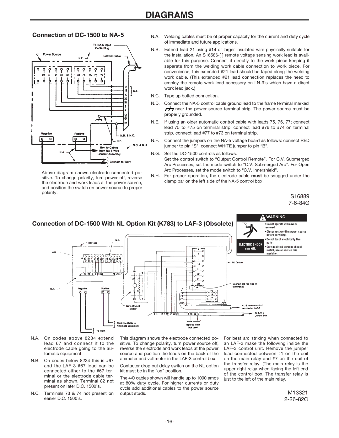
Connection of DC-1500 to NA-5
Above diagram shows electrode connected po- sitive. To change polarity, turn power off, reverse the electrode and work leads at the power source, and position the switch on power source to proper polarity.
N.A. Welding cables must be of proper capacity for the current and duty cycle of immediate and future applications.
N.B. Extend lead 21 using #14 or larger insulated wire physically suitable for the installation. An
N.C. Tape up bolted connection.
N.D. Connect the ![]() near the power source terminal strip. The power source must be
near the power source terminal strip. The power source must be
properly grounded.
N.E. If using an older automatic control cable with leads 75, 76, 77; connect lead 75 to #75 on terminal strip, connect lead #76 to #74 on terminal strip, connect lead #77 to #73 on terminal strip.
N.F. Connect the jumpers on the
N.G. Set the
Set the control switch to “Output Control Remote”. For C.V. Submerged Arc Processes, set the mode switch to “C.V. Submerged Arc”. For Open Arc Processes, set the mode switch to “C.V. Innershield”.
N.H. For proper operation, the electrode cable must be snugged under the clamp bar on the left side of the
S16889
Connection of
![]() WARNING
WARNING
| • Do not operate with covers | |
| removed. | |
| • Disconnect welding power source | |
| before servicing. | |
| • Do not touch electrically live | |
| ||
ELECTRIC SHOCK | parts. | |
• Only qualified persons should | ||
can kill. | ||
install, use or service this | ||
| ||
| machine. |
N.A. On codes above 8234 extend lead 67 and connect it to the electrode cable going to the au- tomatic equipment.
N.B. On codes below 8234 this is #67 and the
N.C. Terminals 73 & 74 not present on earlier D.C. 1500’s.
This diagram shows the electrode connected po- sitive. To change polarity, turn power source off, reverse the electrode and work leads at the power source and position the leads on the back of the ammeter and voltmeter in the
Contactor drop out delay switch on the NL option kit must be in the “on” position.
The 4/0 cables shown will handle up to 1000 amps at 80% duty cycle. For higher currents or duty cycle add additional cables to the power source output studs.
For best arc striking when connected to an
M13321