SYMPTOM |
| CHECK |
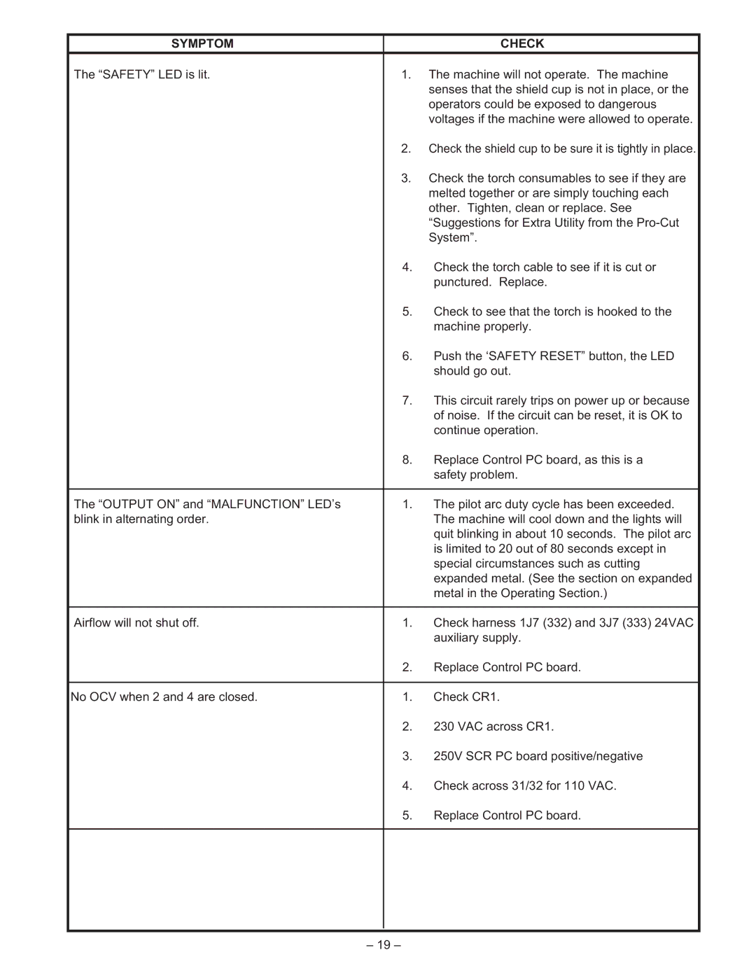
The “SAFETY” LED is lit. | 1. | The machine will not operate. The machine |
|
| senses that the shield cup is not in place, or the |
|
| operators could be exposed to dangerous |
|
| voltages if the machine were allowed to operate. |
| 2. | Check the shield cup to be sure it is tightly in place. |
| 3. | Check the torch consumables to see if they are |
|
| melted together or are simply touching each |
|
| other. Tighten, clean or replace. See |
|
| “Suggestions for Extra Utility from the |
|
| System”. |
| 4. | Check the torch cable to see if it is cut or |
|
| punctured. Replace. |
| 5. | Check to see that the torch is hooked to the |
|
| machine properly. |
| 6. | Push the ‘SAFETY RESET” button, the LED |
|
| should go out. |
| 7. | This circuit rarely trips on power up or because |
|
| of noise. If the circuit can be reset, it is OK to |
|
| continue operation. |
| 8. | Replace Control PC board, as this is a |
|
| safety problem. |
|
|
|
The “OUTPUT ON” and “MALFUNCTION” LED’s | 1. | The pilot arc duty cycle has been exceeded. |
blink in alternating order. |
| The machine will cool down and the lights will |
|
| quit blinking in about 10 seconds. The pilot arc |
|
| is limited to 20 out of 80 seconds except in |
|
| special circumstances such as cutting |
|
| expanded metal. (See the section on expanded |
|
| metal in the Operating Section.) |
|
|
|
Airflow will not shut off. | 1. | Check harness 1J7 (332) and 3J7 (333) 24VAC |
|
| auxiliary supply. |
| 2. | Replace Control PC board. |
|
|
|
No OCV when 2 and 4 are closed. | 1. | Check CR1. |
| 2. | 230 VAC across CR1. |
| 3. | 250V SCR PC board positive/negative |
| 4. | Check across 31/32 for 110 VAC. |
| 5. | Replace Control PC board. |
|
|
|
|
|
|
|
|
|
– 19 –
