AIR INPUT CONNECTIONS
![]() WARNING
WARNING
CYLINDER may explode if damaged
• Keep cylinder upright and chained to a
fixed support.
• Keep cylinder away from areas where it may be damaged.
•Never lift equipment with cylinder attached.
•Never allow the cutting torch to touch cylinder.
•Keep cylinder away from live electrical circuits.
•Maximum inlet pressure 150 psig.
A source of clean compressed air or nitrogen must be supplied to the
Remove the plastic thread protector from the regulator input port (located on the back of the machine). Use a suitable gas connection fitting to make the connection to the available air supply. The input port is a 1/4” (6.3 mm) NPT thread. Tighten the air fitting to prevent leakage but do not overtighten. The use of Teflon tape to seal the connection is recommended.
Nitrogen from cylinders may be used with this machine. The cylinder of nitrogen gas must be equipped with a pressure regulator. No more than 150 psi (1034 kPa) may be supplied to the regulator on the machine. Install a hose between the regulator on the gas cylinder and the gas inlet on the cutter.
OUTPUT CONNECTIONS
![]() WARNING
WARNING
HIGH FREQUENCY SHOCK CAN
CAUSE INJURY OR FALL.
•Keep the cutting torch and cables in good condition.
•Secure yourself in position to avoid a fall.
Torch Connection
The
Pictures of the torch and the required replacement parts are shown in the parts lists in the back of this manual. The ends of the cable to be connected to the power source are unique. Follow the applicable instructions given in Figure 2 in the back of this manu- al.
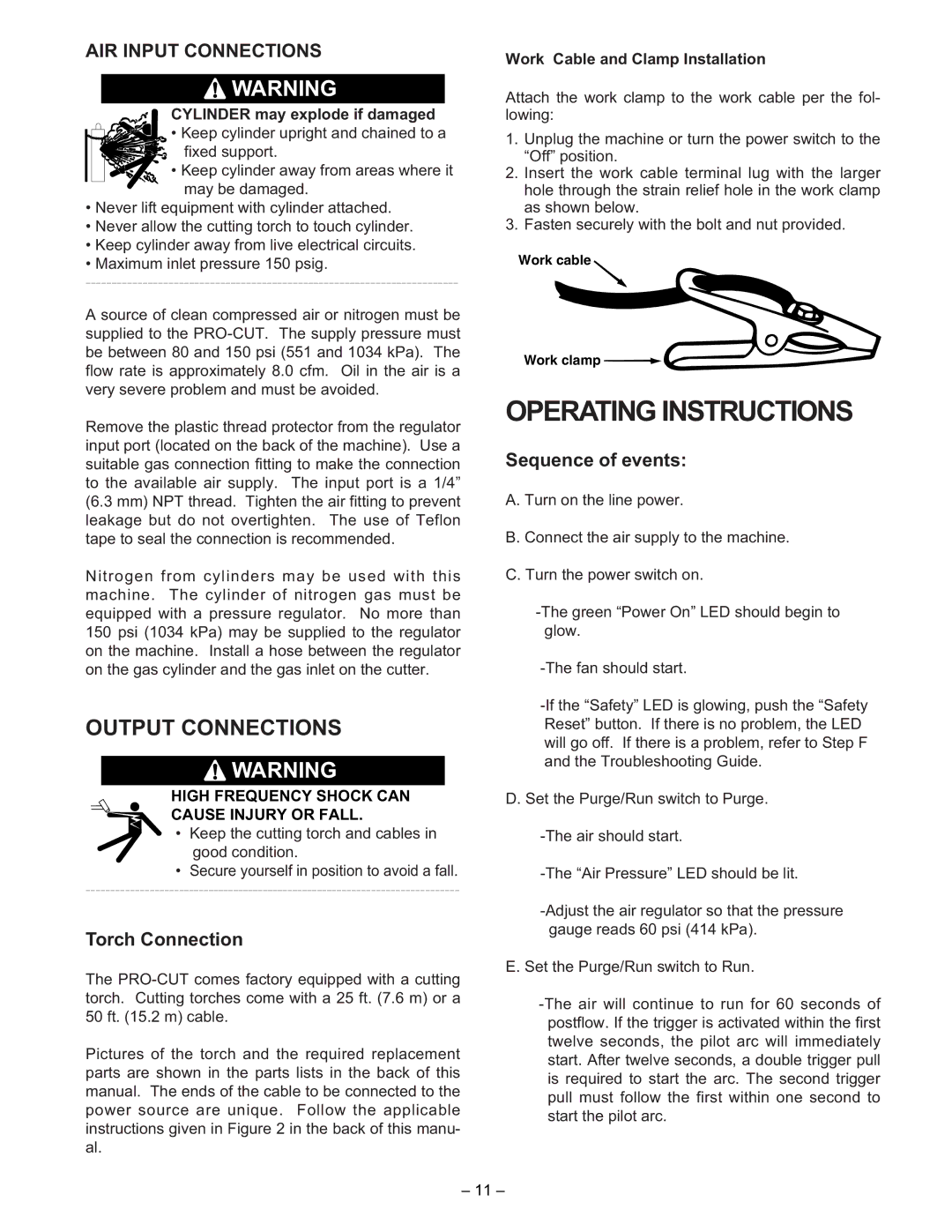
Work Cable and Clamp Installation
Attach the work clamp to the work cable per the fol- lowing:
1.Unplug the machine or turn the power switch to the “Off” position.
2.Insert the work cable terminal lug with the larger hole through the strain relief hole in the work clamp as shown below.
3.Fasten securely with the bolt and nut provided.
Work cable
Work clamp ![]()
![]()
OPERATING INSTRUCTIONS
Sequence of events:
A. Turn on the line power.
B. Connect the air supply to the machine.
C. Turn the power switch on.
D. Set the Purge/Run switch to Purge.
E. Set the Purge/Run switch to Run.
– 11 –