INSTALLATION | ||
|
|
|
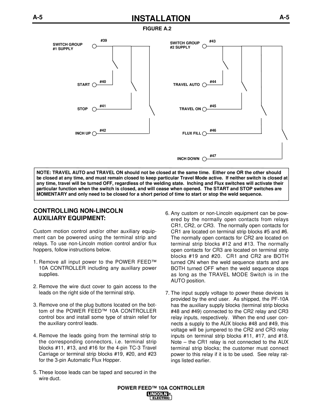
| FIGURE A.2 |
|
SWITCH GROUP #1 SUPPLY
#39
SWITCH GROUP | #43 |
|
|
| |
#2 SUPPLY |
|
|
|
| |
|
|
|
START ![]()
STOP
INCH UP ![]()
#40
#41
#42
TRAVEL AUTO
TRAVEL ON ![]()
FLUX FILL ![]()
INCH DOWN
#44
#45
#46
#47
NOTE: TRAVEL AUTO and TRAVEL ON should not be closed at the same time. Either one OR the other should be closed at any time, and must remain closed to keep particular Travel Mode active. If neither switch is closed at any time, travel will be turned OFF, regardless of the welding state. Inching and Flux switches will activate their particular function when the switch is closed, and will cease when opened. The START and STOP switches are MOMENTARY and only need to be closed for a short period of time to start or stop the weld sequence.
CONTROLLING NON-LINCOLN
AUXILIARY EQUIPMENT:
Custom motion control and/or other auxiliary equip- ment can be powered using the terminal strip and relays. To use
1.Remove all input power to the POWER FEED™ 10A CONTROLLER including any auxiliary power supplies.
2.Remove the wire duct cover to gain access to the leads on the right side of the terminal strip.
3.Remove one of the plug buttons located on the bot- tom of the POWER FEED™ 10A CONTROLLER control box and install some type of strain relief for the auxiliary control leads.
4.Remove the leads going from the terminal strip to the corresponding connectors, i.e. terminal strip blocks #11, #13, and #16 for the
5.These loose leads can be taped and secured in the wire duct.
6.Any custom or
7.The input supply voltage to power these devices is provided by the end user. As shipped, the