OPERATION | ||
|
|
|
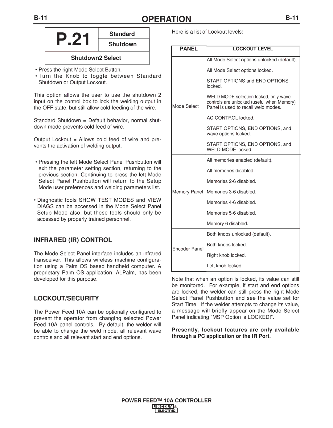
P.21  ShutdownStandard
Shutdown2 Select
•Press the right Mode Select Button.
•Turn the Knob to toggle between Standard Shutdown or Output Lockout.
This option allows the user to use the shutdown 2 input on the control box to lock the welding output in the OFF state, but still allow cold feeding of the wire.
Standard Shutdown = Default behavior, normal shut- down mode prevents cold feed of wire.
Output Lockout = Allows cold feed of wire and pre- vents the activation of welding output.
•Pressing the left Mode Select Panel Pushbutton will exit the parameter setting section, returning to the previous section. Continuing to press the left Mode Select Panel Pushbutton will return to the Setup Mode user preferences and welding parameters list.
•Diagnostic tools SHOW TEST MODES and VIEW DIAGS can be accessed in the Mode Select Panel Setup Mode also, but these tools should only be accessed by properly trained personnel.
INFRARED (IR) CONTROL
The Mode Select Panel interface includes an infrared transceiver. This allows wireless machine configura- tion using a Palm OS based handheld computer. A proprietary Palm OS application, ALPalm, has been developed for this purpose.
LOCKOUT/SECURITY
The Power Feed 10A can be optionally configured to prevent the operator from changing selected Power Feed 10A panel controls. By default, the welder will be able to change the weld mode, all relevant wave controls and all relevant start and end options.
Here is a list of Lockout levels:
PANEL | LOCKOUT LEVEL |
All Mode Select options unlocked (default).
All Mode Select options locked.
START OPTIONS and END OPTIONS locked.
WELD MODE selection locked, only wave
controls are unlocked (useful when Memory) Mode Select Panel is used to recall weld modes.
AC CONTROL locked.
START OPTIONS, END OPTIONS, and wave options locked.
START OPTIONS, END OPTIONS, and
WELD MODE locked.
All memories enabled (default).
All memories disabled.
Memories
Memory Panel Memories
Memories
Memories
Memory 6 disabled.
Both knobs unlocked (default).
Both knobs locked.
Encoder Panel
Right knob locked.
Left knob locked.
Note that when an option is locked, its value can still be monitored. For example, if start and end options are locked, the welder can still press the right Mode Select Panel Pushbutton and see the value set for Start Time. If the welder attempts to change its value, a message will briefly appear on the Mode Select Panel indicating "MSP Option is LOCKED!".
Presently, lockout features are only available through a PC application or the IR Port.
