Return to Section TOC

Section TOC

Return to Master TOC

Master TOC

F-39


F-39


TROUBLESHOOTING AND REPAIR


CURRENT TRANSDUCER TEST (continued)


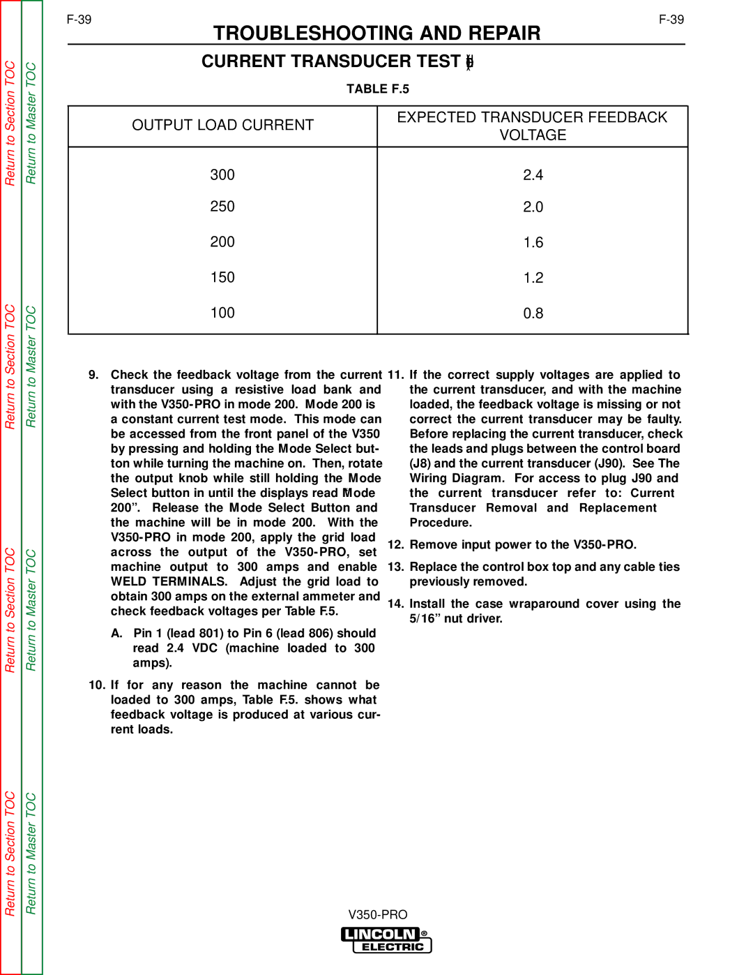
TABLE F.5


EXPECTED TRANSDUCER FEEDBACK


OUTPUT LOAD CURRENT


VOLTAGE


300


2.4


250


2.0


200


1.6


150


1.2


100


0.8


Return to

Return to Section TOC

Return to

Return to Master TOC

9.Check the feedback voltage from the current transducer using a resistive load bank and with the V350-PRO in mode 200. Mode 200 is a constant current test mode. This mode can be accessed from the front panel of the V350 by pressing and holding the Mode Select but- ton while turning the machine on. Then, rotate the output knob while still holding the Mode Select button in until the displays read “Mode 200”. Release the Mode Select Button and the machine will be in mode 200. With the V350-PRO in mode 200, apply the grid load across the output of the V350-PRO, set machine output to 300 amps and enable WELD TERMINALS. Adjust the grid load to obtain 300 amps on the external ammeter and check feedback voltages per Table F.5.

A.Pin 1 (lead 801) to Pin 6 (lead 806) should read 2.4 VDC (machine loaded to 300 amps).

10.If for any reason the machine cannot be loaded to 300 amps, Table F.5. shows what feedback voltage is produced at various cur- rent loads.

11.If the correct supply voltages are applied to the current transducer, and with the machine loaded, the feedback voltage is missing or not correct the current transducer may be faulty. Before replacing the current transducer, check the leads and plugs between the control board (J8) and the current transducer (J90). See The Wiring Diagram. For access to plug J90 and the current transducer refer to: Current

Transducer Removal and Replacement Procedure.

12.Remove input power to the V350-PRO.

13.Replace the control box top and any cable ties previously removed.

14.Install the case wraparound cover using the 5/16” nut driver.

Return to Section TOC

Return to Master TOC

V350-PRO

Page 77
Image 77
Lincoln Electric SVM152-A service manual Output Load Current, Transducer Removal and Replacement Procedure

SVM152-A specifications

The Lincoln Electric SVM152-A is a cutting-edge semi-automatic wire-feed welding machine designed for professionals seeking high performance and efficiency in their welding tasks. This versatile welding system is known for its robust engineering, advanced technology, and user-friendly features, making it a preferred choice for various applications in metal fabrication, automotive repair, and construction.

One of the standout features of the SVM152-A is its impressive versatility. It can accommodate a wide range of welding processes, including MIG, MAG, and FCAW. This flexibility allows users to switch between different welding techniques with ease, providing the adaptability needed for diverse project requirements. Additionally, the machine supports various wire diameters, catering to different welding applications and materials.

The SVM152-A boasts advanced inverter technology, which enhances its performance by increasing efficiency and reducing power consumption. This technology not only leads to lower operational costs but also provides a stable arc and improved weld quality. The inverter design enables the machine to maintain a consistent output, even in challenging conditions, ensuring a smooth welding experience.

Another key characteristic of the Lincoln Electric SVM152-A is its user-friendly interface. The machine features intuitive controls, making it accessible for both seasoned welders and those new to the craft. The digital display provides clear readings of key parameters, such as voltage and wire feed speed, allowing operators to make quick adjustments for optimal weld quality.

The construction of the SVM152-A is designed for durability and reliability. Made from high-quality materials, it can withstand the rigors of demanding work environments. The machine is also equipped with advanced cooling systems to prevent overheating during prolonged use, ensuring a longer lifespan and consistent performance.

Safety is a top priority in the design of the SVM152-A. The machine comes with built-in safety features, including thermal overload protection and circuit breakers, which help protect the equipment and the operator from potential hazards.

In summary, the Lincoln Electric SVM152-A combines versatility, advanced inverter technology, user-friendly controls, robust construction, and safety features, making it an excellent choice for professionals in various industries. Whether tackling intricate welding projects or high-volume production work, the SVM152-A delivers the performance and reliability that modern welders demand.