Master TOC

G-3

ELECTRICAL DIAGRAMS

G-3

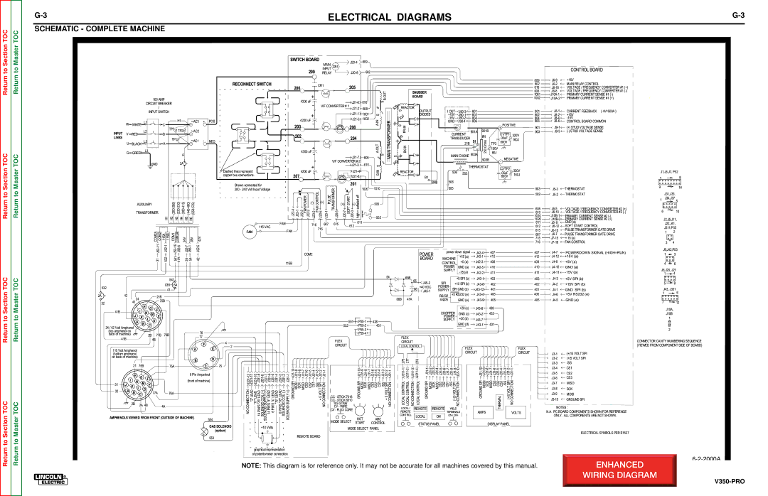
SCHEMATIC - COMPLETE MACHINE


SWITCH BOARD

J20-4

609

MAIN

CR1


INPUT


209 RELAY

J20-8

602

CONTROL BOARD


RECONNECT SWITCH


CR1

205


206


T


+


U


O


100 AMP


-


4200 uF


B


J21-6

616


S


CIRCUIT BREAKER


-

V/F CONVERTER # 1 J21-2


/


608

6


INPUT SWITCH


+


J21-1

1001

S

7


J21-5

1002


L1


H1

AC3

POS

4200 uF


N

TRANSFORMER


-


I

W

C


-

WHITE


203


208


A


L2

TP3

TP2

AC2


INPUT V

B


RED


SNUBBER


BOARD


0

REACTOR

3

X


S


OUTPUT


0

DIODES


2


X


X2

S

IN


-RF


I OUT

J90-3

801


+15V

J90-1

802


-15V

J90-2

804


GND

J90-4

806


CURRENT

901A

901B


POSITIVE

+

C1/TP1

609

J6-9

602

J6-2

616J6-16

608J6-8

1001 J10A-1

1002 J10A-2

801J8-1

802J8-2

804

J8-4

806

J8-6

901

J9-1

903

J9-3

+15V

MAIN RELAY CONTROL

VOLTAGE / FREQUENCY CONVERTER #1 (+) VOLTAGE / FREQUENCY CONVERTER #1 (-) PRIMARY CURRENT SENSE #1 (-)

PRIMARY CURRENT SENSE #1 (+)

CURRENT FEEDBACK ( 4V=500A )

+15V -15V

CONTROL BOARD COMMON

(+)STUD VOLTAGE SENSE (-) STUD VOLTAGE SENSE

LINES


TP1

AC1

NEG

202


204


BLACK L3


U

A


T


+


U


L3


O


MAIN


4200 uF


-


G

GREEN


A


-


A

S


J21-7

605

3


GND


2A


V/F CONVERTER # 2

610


2


+

J21-3

S


Dashed lines represent


J21-4


N


4200 uF


-


I


-


copper bus connections.

207


J21-8


B


Shown connected for


201


200 - 240 Volt Input Voltage


CONTROL


TRANSFORMER


1020

1010

AUXILIARY

208)

230)

415)

460)

575)

POWER

(-)

(+)

PULSE

(+)

START

(-)

softstartoff

505


R1

320V

X3

X1

IN

TRANSDUCER

S1

Ohms

21B


TP3

.05uF 160J 600V


-KB

S

4


X


0


4


X


0

REACTOR


1


X


B1


SNB


21

250

MAIN CHOKE 903A

903B


xxxxxxx


THERMOSTAT

506

503


506


505


150V

80J

- NEGATIVE

C2/TP2 320V

.05uF

600V 160J

503J5-3

502J5-2

THERMOSTAT THERMOSTAT

J1,J6,J7, P52

1 8

916

J31,J33,

1J34,J37

5

Return

Return to Section TOC

Return to Section TOC

Return

Return to Master TOC

Return to Master TOC


TRANSFORMER


(200-


(220-

(380-

(440- (550-


J22-4 J22-1

J22-2 FAN J22-3

J20-2 FAN J20-6

J20-1

J20-5

J20-7 SOFT J20-3

high= xxxxxxx


H1

H2

H3

H4

H5

H6


502


FAN


716

607

615

612

611


115 VAC


715


COM2A COM2


FAN


FAN


115A 115B

COM1

COM1A


24V

28V

42V


J52-11

J52-1

J52-16

J56-6


J52-7 J56-1

J52-5


COM2


541


31

532

41A


24

54

42


115B


541


54


532


CB1 6A


41


2A

42


24


21B


41


75B


32


H


G


F


41B


I N


J


M

E


K

L


D


A


551

P55-1

438


B


C


24 / 42 Volt Amphenol


552

P55-2


431


P55-3


(top amphenol on


76


P55-4


back of machine)


2B


77B

76B


77


41B


4B


4


FLEX


F


CIRCUIT


2


115 Volt Amphenol


A

E


(bottom amphenol


on back of machine)


B

D


21

75B


75A


C

75


H


G

F


6 Pin Ampehnol

J331-12

J331-7

J331-6

J31-8

J31-4

J31-3


MOSI J31-9

J31-8


CS2 J31-5 J31-4

J31-3


I


(front of machine)


N


31


M


J

K


E


L


D


32

A

B


77A

76A


NO CONNECTION "2" LEADJ33111-

"77" LEADJ33110- 14 PIN'S "76" LEADJ3319- SOLENOID COILJ331(+)8- SOLENOID SUPPLY (+)

14 PIN'S "4" LEAD 6 PIN'S "4" LEADJ3315- "75" LEADJ3314- 6 PIN'S "76" LEADJ3313- SOLENOID COILJ331(-)2-

SOLENOIDSUPPLY(-)J331-1 GROUNDSPI-J3110MOSIJ31-9SCK

J31-7MISOCS3-6J31CS2J31-5

CS1

/SS+5VOLTSPI-2J31

CONNECTIONNO J311-


HOTGROUNDSPIJ31-10

SCK

J31-7MISOCS3J31-6

ARCCS1

/SS+5VOLTSPI-2J31

CONNECTIONNO J311-


C


CC - STICK 7018


CC - STICK 6010


2B


2A 4B


4A


TIG GTAW


CV - WIRE


CV - FLUX CORE

AMPHENOLS VIEWED FROM FRONT (OUTSIDE OF MACHINE)

554

MODE SELECT


START

CONTROL


GAS SOLENOID

+10 Volts

MODE SELECT PANEL

(option)


+

553

REMOTE BOARD


graphical representation


of potentiometer connection

POWER

BOARD

65B

65

J45-2


66

+40 VDC


J45-1

66B 41A

power down signal


MACHINE


+15 (a)


+5 (a)

CONTROL


POWER


GND (a)

SUPPLY


-15 (a)


+5 SPI (b)

SPI

+15 SPI (b)

POWER

SPI GND (b)

SUPPLY


RS232

+5 RS232 (e)


supply


GND (e)


+20 (c)

CHOPPER


GND (c)

POWER


+20 (d)

SUPPLY


GND (d)


J42-4 407

J42-1 412

J42-3 408

J42-5 410

J42-2 411

J43-1 403

J43-6 402

J43-12 401

J43-4 406

J43-9 405

J43-8 438

J43-2 432

J43-7

J43-1 431

FLEX

CIRCUIT

LOCAL CONTROL

FLEX


FLEX


CIRCUIT

CIRCUIT

275

277

276


J311-1

J311-2

J311-3

LOCAL CONTROL

LOCAL CONTROL

NO CONNECTION

LOCAL / REMOTE CONTROL

J311-4

J31-1

J31-2 J31-3 J31-4 J31-5

J31-6

J31-7

J31-8

J31-9 J31-10

LOCAL CONTROL

GROUND SPI

MOSI SCK MISO CS3

CS2

CS1

/SS

(+)5 VOLT SPI NO CONNECTION

REMOTE

REMOTE


WELD


TERMINALS

LOCAL

ON


ON / OFF


STATUS PANEL

J31-10

J31-9

GROUND SPI

MOSI

AMPS

J31-8 J31-7

J31-6

J31-5

J31-4

J31-3

J31-2

J31-1

SCK MISO

CS3

THERMAL

/SS

(+)5VOLT SPI

CONNECTIONNO


CS2

CS1


VOLTS

DISPLAY PANEL

605

J6-5

VOLTAGE / FREQUENCY CONVERTER #2 (+)

610

J6-10

VOLTAGE / FREQUENCY CONVERTER #2 (-)

1010

J10B-1

PRIMARY CURRENT SENSE #2 (-)

1020

J10B-2 PRIMARY CURRENT SENSE #2 (+)

611

J6-11

GND (a)

612

J6-12

SOFT START CONTROL

615

J6-15

PULSE TRANSFORMER GATE DRIVE

607

J6-7

PULSE TRANSFORMER GATE DRIVE

715

J7-15

+ 15 (a)

716

J7-16

FAN CONTROL

407J4-7POWERDOWN SIGNAL (HIGH=RUN)

412J4-12+15V (a)

408

J4-8

+5V (a)

410

J4-10

GND (a)

411

J4-11

-15V (a)

403J4-3+5V SPI (b)

402

J4-2

+15V SPI (b)

401J4-1GND SPI (b)

406J4-6+5V RS232 (e)

405

J4-5GND (e)

J3-1

(+)15 VOLT SPI

J3-2

(+)5 VOLT SPI

J3-3

/SS

J3-4

CS1

J3-5

CS2

J3-6

CS3

J3-7

MISO

J3-8

SCK

J3-9

MOSI

J3-10

GROUND SPI

NOTES :

N.A. PC BOARD COMPONENTS SHOWN FOR REFERENCE ONLY. ALL COMPONENTS ARE NOT SHOWN.

ELECTRICAL SYMBOLS PER E1537

6 10

J2,J5,J11,

J22,J41,

J311,P55

12

34

J9,J42,P53

1 3

4 6

J8,J20, J21

14

5 8

J43, J331

1 6

712

J10A,

J10B

1

2

CONNECTOR CAVITY NUMBERING SEQUENCE (VIEWED FROM COMPONENT SIDE OF BOARD)

6-2-2000A

NOTE: This diagram is for reference only. It may not be accurate for all machines covered by this manual.

V350-PRO

Page 135
Image 135
Lincoln Electric SVM152-A service manual Schematic Complete Machine, Return to To Section TOC

SVM152-A specifications

The Lincoln Electric SVM152-A is a cutting-edge semi-automatic wire-feed welding machine designed for professionals seeking high performance and efficiency in their welding tasks. This versatile welding system is known for its robust engineering, advanced technology, and user-friendly features, making it a preferred choice for various applications in metal fabrication, automotive repair, and construction.

One of the standout features of the SVM152-A is its impressive versatility. It can accommodate a wide range of welding processes, including MIG, MAG, and FCAW. This flexibility allows users to switch between different welding techniques with ease, providing the adaptability needed for diverse project requirements. Additionally, the machine supports various wire diameters, catering to different welding applications and materials.

The SVM152-A boasts advanced inverter technology, which enhances its performance by increasing efficiency and reducing power consumption. This technology not only leads to lower operational costs but also provides a stable arc and improved weld quality. The inverter design enables the machine to maintain a consistent output, even in challenging conditions, ensuring a smooth welding experience.

Another key characteristic of the Lincoln Electric SVM152-A is its user-friendly interface. The machine features intuitive controls, making it accessible for both seasoned welders and those new to the craft. The digital display provides clear readings of key parameters, such as voltage and wire feed speed, allowing operators to make quick adjustments for optimal weld quality.

The construction of the SVM152-A is designed for durability and reliability. Made from high-quality materials, it can withstand the rigors of demanding work environments. The machine is also equipped with advanced cooling systems to prevent overheating during prolonged use, ensuring a longer lifespan and consistent performance.

Safety is a top priority in the design of the SVM152-A. The machine comes with built-in safety features, including thermal overload protection and circuit breakers, which help protect the equipment and the operator from potential hazards.

In summary, the Lincoln Electric SVM152-A combines versatility, advanced inverter technology, user-friendly controls, robust construction, and safety features, making it an excellent choice for professionals in various industries. Whether tackling intricate welding projects or high-volume production work, the SVM152-A delivers the performance and reliability that modern welders demand.