Return to Section TOC
Return to Section TOC
Return to Master TOC
Return to Master TOC
TROUBLESHOOTING & REPAIR
MODE BOARD
REMOVAL AND REPLACEMENT (continued)
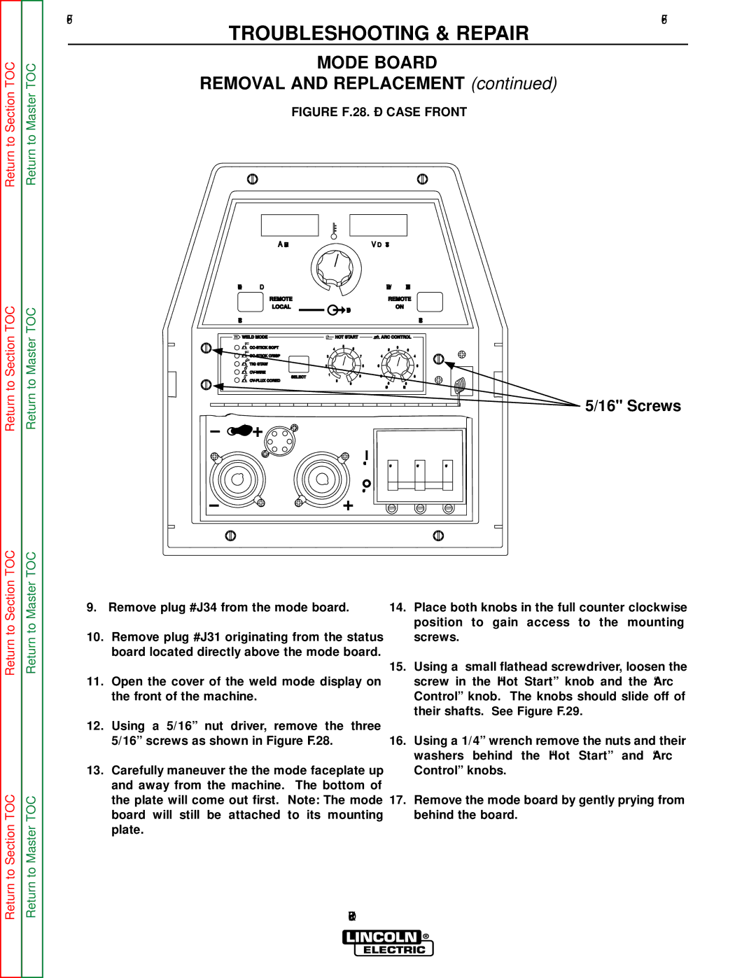
FIGURE F.28. – CASE FRONT
AMPS |
|
| VOLTS |
| |
CONTROL |
|
| WELD TERMINALS | ||
REMOTE |
|
| REMOTE | ||
LOCAL |
| OUTPUT | ON | ||
|
|
| |||
SELECT |
|
|
| SELECT | |
m WELD MODE |
| HOT START | ARC CONTROL | ||
| 5 |
| 0 | ||
4 | 6 | ||||
|
| +2 | |||
3 | 7 | +4 | |||
TIG GTAW | 2 | 8 | +6 | ||
| |||||
1 | 9 |
| |||
SELECT | +8 | ||||
| |||||
| 0 | +10 | |||
|
| 10 | |||
|
|
| SOFT | CRISP | |
5/16" Screws
ON
OFF | OFF | OFF |
OFF
Return to Section TOC
Return to Section TOC
Return to Master TOC
Return to Master TOC
9.Remove plug #J34 from the mode board.
10.Remove plug #J31 originating from the status board located directly above the mode board.
11.Open the cover of the weld mode display on the front of the machine.
12.Using a 5/16” nut driver, remove the three 5/16” screws as shown in Figure F.28.
13.Carefully maneuver the the mode faceplate up and away from the machine. The bottom of the plate will come out first. Note: The mode board will still be attached to its mounting plate.
14.Place both knobs in the full counter clockwise position to gain access to the mounting screws.
15.Using a small flathead screwdriver, loosen the screw in the “Hot Start” knob and the “Arc Control” knob. The knobs should slide off of their shafts. See Figure F.29.
16.Using a 1/4” wrench remove the nuts and their washers behind the “Hot Start” and “Arc Control” knobs.
17.Remove the mode board by gently prying from behind the board.