TOC

TOC

G-9

ELECTRICAL DIAGRAMS

G-9

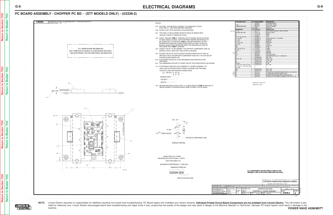
PC BOARD ASSEMBLY - CHOPPER PC BD - (STT MODELS ONLY) - (G3339-2)

2-G3339

ENGINEERING CONTROLLED

CHANGE DETAIL: REVISED MAKE SPECIFICATION

MANUFACTURER:

No


P.C. BOARD BLANK INFORMATION

BUY COMPLETE AS G3339-D (2 LAYER BOARD PER E3281) (SEE ELECTRONIC FILE FOR ADDITIONAL INFORMATION)

NOTES :

N.A. CAUTION: THIS DEVICE IS SUBJECT TO DAMAGE BY STATIC ELECTRICITY. SEE E2454 BEFORE HANDLING.

N.B. DO NOT COAT WITH ENCAPSULATION MATERIAL.

N.C. THIS AREA TO BE COVERED ON BOTH SIDES OF BOARD WITH SEALANT PRIOR TO ENCAPSULATION.

N.D. INJECT SEALANT ITEM 4 THROUGH THE PC BOARD HOLES (6 HOLES) TO SEAL MODULE LEADS. CAVITY BETWEEN BOARD AND MODULE TO BE COMPLETELY FILLED WITH ITEM 4 SEALANT MATERIAL AS PER APPROPRIATE MANUFACTURING WORK INSTRUCTIONS. COVER ALL

MODULE LEADS THAT PROTRUDE FROM THE NON-MODULE SIDE OF THE BOARD WITH ITEM 4 SEALANT.

N.E. FEMALE EYELET TO BE AGAINST THE OPPOSITE COMPONENT SIDE AS SHOWN. EYELET MUST NOT SPIN AFTER CLINCHING.

N.F. SOLDER EYELET SO THAT SOLDER COVERS ENTIRE EYELET AND ALL AROUND EYELET ON OPPOSITE COMPONENT SIDE ONLY. NO ICICLES OR SOLDER BLOBS PERMITTED.

N.G. ELECTRONIC MODULES TO BE ASSEMBLED AND ENCAPSULATED PER E3875.

N.H. THIS DIMENSION APPLIES TO THESE TWO OF THE FOUR EYELETS AS SHOWN.

N.J. ELECTRONIC MODULES ON A COMMON P.C. BOARD ASSEMBLY TO HAVE VGE(TH) WITHIN 5 SORT CODES (0.5VSPAN) FOR THE SAME VCE(SAT) CODE AND MANUFACTURING CODE.

e.g. M21214-1 X XX XX ........

VENDOR CODE

VCE(SAT)


ITEM (USED WITH)*

QTY

PART NUMBER

DESCRIPTION

1


1

G3339-D

PC BOARD BLANK

2

(X4)*

1

S20590-1

HEAT SINK, TO-220

3

(B48,B49,B53,B55)*

4

T9147-11

EYELET, FEMALE

4


2 oz.

E2861

SEALANT


REFERENCES

QTY

PART NO.

DESCRIPTION

N.A.,N.J.

A1, A2

2

M21214-1

ELECTRONIC MODULE,7 IGBT(T12704-85)


B48, B49, B53, B55

4

T9147-15

EYELET, MALE


C1

1

T11577-49

500/50


C2

1

S13490-8

50/25


C3, C7, C9, C10, C21

5

S16668-11

.1/50


C6, C8, C20

3

S13490-173

CAPACITOR,MPF,1.0 uF,63VDC


C11, C14

2

S16668-10

4700pF/50


C12, C17

2

S16668-7

820pF/50


C13, C15, C16

3

S16668-3

100pF/100


C18, C19

2

S20500-2

.47/630


C22

1

S16668-9

150pF/100


C23

1

S13490-25

4.7/35


D1, D2, D3, D4, D7

5

T12199-1

1N4004


D5, D6

2

T12705-23

1N5818


DZ1

1

T12702-29

1N4744A

N.B.

J10

1

S20351-6

HEADER


OCI1

1

S15000-10

OPTO ISOLATOR


R1

1

S18380-5

THERMISTOR,PTC,0.5-1.17 OHMS,0.5A


R2

1

S19400-3320

332 1/4W


R3, R4, R27

3

S19400-3321

3.32K 1/4W


R5

1

S19400-4752

47.5K 1/4W


R6

1

S19400-4750

475 1/4W


R8, R23

2

S19400-4751

4.75K


R9, R10, R11, R12, R13, R14,

14

S19400-3010

301 1/4W


R15, R16, R17, R18, R19, R20,


R21, R22


R25

1

S19400-2213

221K 1/4W


R26

1

S19400-3323

332K 1/4W

N.A.

X1

1

S15018-9

IC,CMOS,MULTIVIBRATOR,MONOSTABLE,DUAL,4538 (SS)

N.A.

X2

1

S15018-21

IC,DRIVER,9A LOW-SIDE MOSFET (SS)

N.A.

X3

1

S15018-15

IC,CMOS,GATE,NAND,2-INPUT,QUAD,SCHM (SS)


X4

1

S15128-6

IC,SMD,VOLT REG,FIXED,3-TERMINAL,POS VOLT,1A,15V

Return to

Return to Section TOC

Return to Section TOC

Return to

Return to Master TOC

Return to Master TOC

N.G.

.490 ±.005 (RESTRAINED)

N.H.

5.50 ±.04

B48

N.D.

xxxxxxx x x

x


x

x


x

x


x

x


x

x


x

x

C19

x

x


x

x


x

x


x

x


x

x


x

xxxxxxxx x xx

2

N.H.

B53

.45

0

1.30

0

N.C.


R16


R23


R15


R8


D6


C10


C6


DZ1


D5


C7


C21


R17


X2


R14


R26

R5


C9


X1


C8


C17


C23


D7


R18


R13


C16


R6


C20


X3


C3

C14


R19

R3

R4

C12

C13

C15


R12

R27


C1


R20


X4


C2


R11


R25


R21


R10


C11


C22


OCI1


D4

D3

D2

D1


R22


R2


R1

R9


J10


N.B.

4.00

1


B49

xxxxxxxx x xx

CHOPPER G3339-2

x


x


x


x

STT

x


x

x


x


x

C18

x


x


x


x


x


x


x


x


x


x


x

N.K.

xxxxxxxx x xx


N.H.

B55

1.30

7.50 ±.04

VGE(TH)

N.K. BEFORE ENCAPSULATION, APPLY A .19 WIDE BEAD OF ITEM 4 SEALANT IN AREAS SHOWN TO ANCHOR CAPACITORS C18 AND C19 (2 PLACES).

N.E., N.F.

3

R .045


.275


.285

.116MAX. CRIMP HEIGHT

OPPOSITE COMPONENT SIDE

CAPACITORS = MFD/VOLTS RESISTORS = OHMS

EYELET DETAIL

MAKE PER E1911-ROHS

ENCAPSULATE WITH E1844 (1 COAT)

TEST PER E3647-CH

SCHEMATIC REFERENCE: L11340-2D0

MANUFACTURED AS:

G3339-2D0


ALL COMPONENTS AND MATERIALS USED IN THIS


ASSEMBLY ARE TO BE RoHS COMPLIANT PER E4253.


IDENTIFICATION CODE


FOR PARTS ORDERS AND SUBSIDIARY ORDERS:


INCLUDE (1) S25191PRINT AND (1) T12837-1.


THIS DOCUMENT CONTAINS PROPRIETARY INFORMATION OWNED BY LINCOLN GLOBAL, INC. AND MAY NOT BE DUPLICATED, COMMUNICATED

PROPRIETARY & CONFIDENTIAL:


TO OTHER PARTIES OR USED FOR ANY PURPOSE WITHOUT THE EXPRESS WRITTEN PERMISSION OF LINCOLN GLOBAL, INC.


UNLESS OTHERWISE SPECIFIED TOLERANCE

DESIGN INFORMATION

REFERENCE: EQUIPMENT TYPE:


INVERTER WELDERS

PAGE ___ OF ___

ON 2 PLACE DECIMALS IS ± .02


MANUFACTURING TOLERANCE PER E2056


1

1

ON 3 PLACE DECIMALS IS ± .002

DRAWN BY:

FEI

G3339-1

SUBJECT:

CHOPPER P.C. BOARD ASSEMBLY

DOCUMENT


DOCUMENT

ON ALL ANGLES IS ± .5 OF A DEGREE

ENGINEER:


SCALE:

NUMBER:


REVISION:

MATERIAL TOLERANCE ("t ") TO AGREE


G3339-2


A

WITH PUBLISHED STANDARDS.


MATERIAL

APPROVAL


PROJECT


DO NOT SCALE THIS DRAWING

APPROVED:

-

1:1

DISPOSITION: UF

DATE:

10/2/2006

NUMBER: CRM34409


STRP

SOLID EDGE

NOTE: Lincoln Electric assumes no responsibility for liablilities resulting from board level troubleshooting. PC Board repairs will invalidate your factory warranty. Individual Printed Circuit Board Components are not available from Lincoln Electric. This information is pro- vided for reference only. Lincoln Electric discourages board level troubleshooting and repair since it may compromise the quality of the design and may result in danger to the Machine Operator or Technician. Improper PC board repairs could result in damage to the

machine.

POWER WAVE 455M/MSTT

Page 143
Image 143
Lincoln Electric SVM173-A service manual PC Board Assembly Chopper PC BD STT Models only G3339-2

SVM173-A specifications

The Lincoln Electric SVM173-A is a highly regarded welding power supply that stands out for its advanced features, robust performance, and innovative technologies. This machine is specifically designed to meet the demands of both industrial and commercial welding applications, making it a versatile choice for professionals.

One of the main features of the SVM173-A is its high efficiency, which contributes to reduced energy costs and enhanced productivity. The device operates on a powerful DC output, ensuring stable and reliable arc performance. This is particularly beneficial when working with various materials, allowing for smooth and consistent welds.

The SVM173-A leverages Lincoln Electric's proprietary inverter technology. This innovation allows for a lighter weight and more compact design without compromising on power. The inverter technology also enables precise control of the welding parameters, which is critical for maintaining quality across different welding tasks. Additionally, the machine features a wide input voltage range, accommodating various power sources and enhancing its adaptability on job sites.

Another key characteristic of the SVM173-A is its user-friendly interface. The machine is equipped with an intuitive control panel that allows users to easily adjust settings, making it accessible for both novice and experienced welders. The digital display provides clear readouts of output parameters and error notifications, facilitating quick troubleshooting in the field.

Safety is paramount in welding operations, and the SVM173-A incorporates several protection features. These include overcurrent protection, overheating protection, and circuit protection, ensuring that the machine operates safely and efficiently under various conditions.

The SVM173-A also supports a wide range of welding processes, including MIG, TIG, and stick welding. This flexibility makes it an ideal choice for workshops that require a multi-process machine capable of handling diverse applications. Furthermore, the SVM173-A supports spool gun operation, which is particularly useful for aluminum welding, enhancing its versatility even further.

In summary, the Lincoln Electric SVM173-A is a powerful and adaptable welding machine that combines innovative technologies, user-friendly features, and robust safety mechanisms. Its high efficiency, precision control, and multi-process capabilities make it an excellent investment for professionals seeking reliable performance in demanding environments. Whether for heavy-duty industrial use or more specialized applications, the SVM173-A stands as a testament to Lincoln Electric's commitment to quality and innovation in welding solutions.