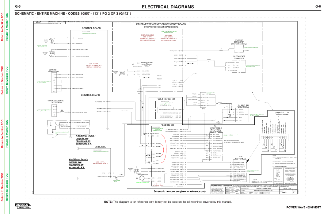
Lincoln Electric SVM173-A Schematic Entire Machine Codes 10957 11311 PG 2 of 3 G4421

Models: SVM173-A

1 165
Download 165 pages 33.5 Kb
Page 140
Image 140

TOC

TOC

G-6

ELECTRICAL DIAGRAMS

G-6

SCHEMATIC - ENTIRE MACHINE - CODES 10957 - 11311 PG 2 OF 3 (G4421)

G4421

ENGINEERING CONTROLLED

CHANGE DETAIL: CONTROL BOARD, CHANGED 2J4 TO 3J4

MANUFACTURER:

No


CONTROL BOARD

ETHERNET/DEVICENET OR DEVICENET BOARD

(ETHERNET/DEVICENET BOARD SHOWN)

Schematic: G3893

Schematic: G3789

Located on left side of control box

Located on rear, left side of front door

see page 3 for details

2B

2B

YELLOW


THERMAL


LED


2W

2W

Located by power switch.

See page 3 for details

1W

1W

RED/GREEN


STATUS


LED


1B

1B

S3 RS232

CONNECTOR


2

253


253


3

254


254


4


Located under spring loaded cover


see page 3 for details

5


6


251


251


7


20


8J7 THERMAL LED

7J7 THERMAL LED

3J7 STATUS LED (HI FOR RED)

4J7 STATUS LED (HI FOR GREEN)

LEDS - 10 TOTAL

DIP SWITCH - 1 BANK OF 8

SEE PAGE 3 FOR DETAILS

3J2 RS232 RECEIVE

4J2 RS232 TRANSMIT

1J2

RS232 COMMON

RED/GREEN

STATUS

LED

830

6B

6W


ETHERNET/DEVICENET

DEVICENET


LEDS - 12 TOTAL

LEDS - 9 TOTAL


DIP SWITCH - 4 BANKS OF 8

DIP SWITCH - 2 BANKS OF 8


SEE PAGE 3 FOR DETAILS

SEE PAGE 3 FOR DETAILS


ETHERNET PORT

J710


+24VDC

5J75

894


0 VDC

2J75

893


ETHERNET/DEVICENET BOARD

CAN_H

1J75

892

1J76


ONLY


DEVICENET CONFIGURATION

CAN_L

4J75

891


MUST BE IN FOR

3J76


DEVICENET


1J74


(HIGH for RED)


2J74


(HIGH for GREEN)


N.C.


ARCLINK L


ARCLINK H


ARCLINK L

3J73


ARCLINK H

4J73


ARCLINK L

1J73


0 VDC

2J73


ARCLINK H


+40VDC


1J72

2J72

3J72

4J72


ETHERNET

CONNECTOR

(Ethernet Board only)

Located under spring loaded cover

L10

RJ45 type

S5 DEVICENET

CONNECTOR

L2

894

2

+24VDC


893

3

0 VDC

Located under spring loaded cover


See page 3 for details

892

4

CAN_H


891

5

CAN_L


S2 VOLTAGE SENSE RECEPTACLE

CONTROL BOARD

VOLTAGE SENSE

4J9

67

743


Located behind front


ARCLINK +

3J16

door panel.


154B

54A


VOLT SENSE BD

ARCLINK - 153B

1J16

53A


ELECTRODE SENSE

5J16

67A


N.D.

741


67B


800

Schematic:S24779

+40VDC

6J16


N.E.

840

Located on rear, right side of front door

52B

52A


see page 3 for details

0 VDC


L7

S1 ARCLINK


VOLTAGE SENSE OUTPUT

4J16

51A


51B


Return

Return to Section TOC

Return to Section TOC

Return to Section TOC

Return

Return to Master TOC

Return to Master TOC

Return to Master TOC

52A

53A

Located under spring loaded cover See page 3 for details

1

2L4

3

21A

21A

4

C422-1

GROUND LEAD

CURRENT SENSOR

C422-2


ARC LINK H

6J9

WORK VOLTAGE SENSE

ARC LINK L


3J6 GROUND CURRENT SENSE

CURRENT SENSOR CLOSED

IS THE FAULT CONDITION

11J6 GROUND CURRENT SENSE

1J11

2J11

54

53


J16

51A

54A

RECEPTACLE


WIRE FEEDER VOLTAGE SENSE

1J2

67B


53

A ARCLINK -


ROBOTIC VOLTAGE SENSE 3J1

67C


54

B ARCLINK +


jumper 9,10,11 for


67

C ELECTRODE SENSE

Located under spring loaded cover

welder to operate


See page 3 for details

VOLTAGE SENSE SELECT (+)

1J1

512


L6


VOLTAGE SENSE SELECT (-)

4J1

511


52

D +40VDC


L5

51

E 0 VDC


FEED HD BD


S6


Schematic: G3823


WIREFEEDER


Located on rear, right side


of front door

VOLTAGE SENSE SELECT (-)

14J85 511


INTERFACE


see page 3 for details


VOLTAGE SENSE SELECT (+)

13J85


RECEPTACLE


Located on vertical panel near lift bale

N.F.

Additional input / outputs are illustrated on schematic # 1.

DC BUS BD


512


840

4J81

+40VDC

+15VDC TACH

1J84

841

841

A

TACH +15VDC

Located under spring loaded cover


See page 3 for details

800

3J81


844


0 VDC

TACH COMMON

4J84

844

B

TACH COMMON


TACH 1A DIFF. INPUT

2J84

842

842

C TACH 1A DIFF SIGNAL


TACH 1B DIFF. INPUT

3J84

843

843

D TACH 1B DIFF SIGNAL TACH signals are selected


TACH 2A DIFF. INPUT

5J84


845


by software ( standard or Diff type )

741

2J81

ARCLINK H

845

E

TACH 2A DIFF SIGNAL


ARCLINK L

TACH 2B DIFF. INPUT

6J84

846

846

F TACH 2B DIFF SIGNAL


743

1J81


SINGLE TACH INPUT

7J84

847

847

G

SINGLE TACH INPUT


EN-170

Schematic: M19330

Located on rear of control box (right)

Additional input /


outputs are

LEDS - 1 TOTAL


illustrated on

SEE PAGE 3 FOR DETAILS


schematic # 1.


0 VDC

1J47


+40VDC FEEDER

3J47

51

50

52

CB1

10A

located on lower left case front


MOTOR "+"


67C

I

VOLTAGE SENSE


1J83

539

539

J

MOTOR "+"


154B

2J82

ARCLINK H

MOTOR "-"

2J83

541

541

K

MOTOR "-"


SOLENOID +40VDC

3J83

521

521

N

SOLENOID +40VDC


S7 I/O


NOTES:


ARCLINK L


153B

1J82


N.C. IF FEEDHEAD BOARD IS NOT PRESENT, INSERT


SOLENOID INPUT

4J83

522

522

P

SOLENOID INPUT


RECEPTACLE


P82 INTO J73.


GND-A

T


51B

3J82

0 VDC


N.D. COMMUNICATION INTERFACE MODULE.


TRIGGER +15VDC

1J85

851


851

1 TRIGGER +15VDC


N.E. ROBOTIC WIRE DRIVE INTERFACE MODULE.


52B

4J82

+40VDC

TRIGGER INPUT

2J85

852


852

2 TRIGGER INPUT


DUAL PROC. INPUT

3J85

853


853

3 DUAL PROC. INPUT


N.F. K2202-4 MACHINES ONLY.


RED/GREEN

5W

15J85

(HIGH for RED)

4 STEP INPUT

4J85

854


854

4

4 STEP INPUT


LEAD COLORCODE:

COMPONENTVALUE UNITS:


COLD INCH +15VDC

5J85

855


855

5 COLD INCH +15VDC


STATUS


Located under spring loaded cover


B-BLACK

CAPACITOR: MFD/VOLTS


LED

5B

16J85

(HIGH for GREEN)

COLD IN. FORWARD

6J85

856


856

6

COLD IN. FORWARD

See page 3 for details


G-GREEN

RESISTOR: OHMS/WATTS


O-ORANGE


COLD IN. REVERSE

7J85

857


857

7

COLD IN. REVERSE


R-RED

CONNECTORPIN NUMBERS:


Blocking Diode for Motor


U-BLUE


858

8 GAS PURGE INPUT


GAS PURGE INPUT

8J85

858


W-WHITE

EX. 12 PIN CONNECTOR


859

9 SHUTDOWN +15VDC


Y-YELLOW


SHUTDOWN +15VDC


1

2

6


D6

886

5J83

+40VDC

9J85

859


860

10 SHUTDOWN 1 INPUT


LABELS:


861


SHUTDOWN 1 INPUT 10J85

860


11 SHUTDOWN 2 INPUT


LEGEND


COMMON


862

12 INPUT B


7


12


880

6J83

+40VDC


DASHED = "

" STT MACHINE ONLY

FRAME GROUND


SHUTDOWN 2 INPUT

11J85

861


LATCH


Located on rear of control box (center)


PHANTOM= "

" OPTION


EARTH GROUND

VIEW OF CONNECTORON PC BOARD


DIP SWITCHES


INPUT B

12J85

862


(see other sheet for use )


THIS DOCUMENT CONTAINS PROPRIETARY INFORMATION OWNED BY LINCOLN GLOBAL, INC. AND MAY NOT BE DUPLICATED, COMMUNICATED


PROPRIETARY & CONFIDENTIAL:


TO OTHER PARTIES OR USED FOR ANY PURPOSE WITHOUT THE EXPRESS WRITTEN PERMISSION OF LINCOLN GLOBAL, INC.


THE INFORMATION ON THIS

DESIGN INFORMATION

REFERENCE: EQUIPMENT TYPE:


INVERTER WELDERS


PAGE

2

OF 3


PRINT IS FOR REFERENCE

DRAWN BY:

F.Valencic


G4050

SUBJECT:


455M MACHINE SCHEMATIC

DOCUMENT


DOCUMENT

EDGE


Schematic numbers are given for reference only.

ONLY. COMPONENTS AND


ENGINEER:

S.Poole

SCALE:


NUMBER:


REVISION:


CIRCUITRY MAY BE DIFFERENT

MATERIAL


APPROVAL


PROJECT

G4421


F


SOLID


FROM AN ACTUAL MACHINE.

APPROVED:

.


NONE

DISPOSITION:

UF

DATE:


2/1/2007

NUMBER: CRM22115-GC


NOTE: This diagram is for reference only. It may not be accurate for all machines covered by this manual.

POWER WAVE 455M/MSTT

Page 140
Image 140
Lincoln Electric SVM173-A service manual Schematic Entire Machine Codes 10957 11311 PG 2 of 3 G4421

SVM173-A specifications

The Lincoln Electric SVM173-A is a highly regarded welding power supply that stands out for its advanced features, robust performance, and innovative technologies. This machine is specifically designed to meet the demands of both industrial and commercial welding applications, making it a versatile choice for professionals.

One of the main features of the SVM173-A is its high efficiency, which contributes to reduced energy costs and enhanced productivity. The device operates on a powerful DC output, ensuring stable and reliable arc performance. This is particularly beneficial when working with various materials, allowing for smooth and consistent welds.

The SVM173-A leverages Lincoln Electric's proprietary inverter technology. This innovation allows for a lighter weight and more compact design without compromising on power. The inverter technology also enables precise control of the welding parameters, which is critical for maintaining quality across different welding tasks. Additionally, the machine features a wide input voltage range, accommodating various power sources and enhancing its adaptability on job sites.

Another key characteristic of the SVM173-A is its user-friendly interface. The machine is equipped with an intuitive control panel that allows users to easily adjust settings, making it accessible for both novice and experienced welders. The digital display provides clear readouts of output parameters and error notifications, facilitating quick troubleshooting in the field.

Safety is paramount in welding operations, and the SVM173-A incorporates several protection features. These include overcurrent protection, overheating protection, and circuit protection, ensuring that the machine operates safely and efficiently under various conditions.

The SVM173-A also supports a wide range of welding processes, including MIG, TIG, and stick welding. This flexibility makes it an ideal choice for workshops that require a multi-process machine capable of handling diverse applications. Furthermore, the SVM173-A supports spool gun operation, which is particularly useful for aluminum welding, enhancing its versatility even further.

In summary, the Lincoln Electric SVM173-A is a powerful and adaptable welding machine that combines innovative technologies, user-friendly features, and robust safety mechanisms. Its high efficiency, precision control, and multi-process capabilities make it an excellent investment for professionals seeking reliable performance in demanding environments. Whether for heavy-duty industrial use or more specialized applications, the SVM173-A stands as a testament to Lincoln Electric's commitment to quality and innovation in welding solutions.