Section TOC

Master TOC

G-7


ELECTRICAL DIAGRAMS


G-7

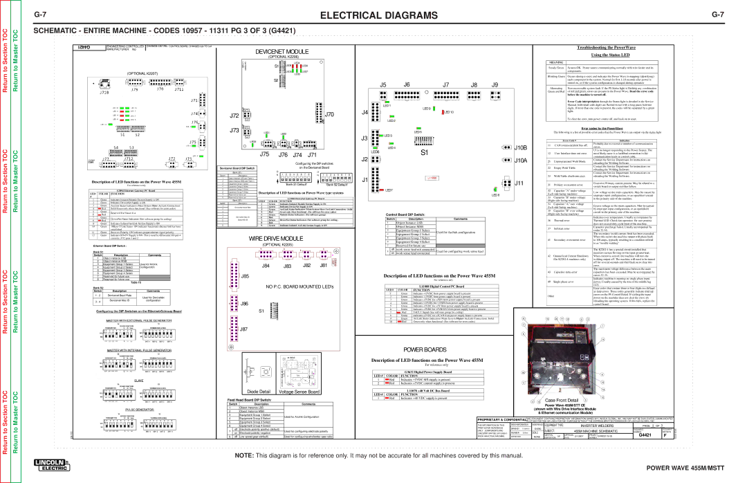
SCHEMATIC - ENTIRE MACHINE - CODES 10957 - 11311 PG 3 OF 3 (G4421)


G4421

ENGINEERING CONTROLLED

CHANGE DETAIL: CONTROL BOARD, CHANGED 2J4 TO 3J4


Troubleshooting the PowerWave


MANUFACTURER: No


DEVICENET MODULE


Using the Status LED


(OPTIONAL K2206)


GATEWAY L11046

S1

LED6

LED4

LED8


(OPTIONAL K2207)


LED5

LED7


LED3

S2

J5

J6

J7

J8

J9


LED 1


J72


J4

LED 9

J72

J70

LED 10


J70

LED 2


MEANING


Steady Green

System OK. Power source communicating normally with wire feeder and its


components.


Blinking Green

Occurs during a reset, and indicates the Power Wave is mapping (identifying)


each component in the system. Normal for first 1-10 seconds after power is


turned on, or if the system configuration is changed during operation


Alternating

Non-recoverable system fault. If the PS Status light is flashing any combination

Green and Red

of red and green, errors are present in the Power Wave. Read the error code


before the machine is turned off.


Error Code interpretation through the Status light is detailed in the Service


Manual. Individual code digits are flashed in red with a long pause between


digits. If more than one code is present, the codes will be separated by a green


light.


To clear the error, turn power source off, and back on to reset.

TOC

TOC

J73

J73


LED1

LED2


LED9


J75

J76

J74

J71


J75 J76 J74 J71

J3

J2


LED 3

LED 5


LED6

LED 4

S1


Error codes for the PowerWave


The following is a list of possible error codes that the Power Wave can output via the status light


Error Code #

Indication

J10B

11

CAN communication bus off.

Probably due to excessive number of communication


errors.


UI is no longer responding to the Power Source. The


12

User Interface time out error.

most likely cause is a fault/bad connection in the

J10A


communication leads or control cable.

21

Unprogrammed Weld Mode.

Contact the Service Department for instructions on


Description of LED functions on the Power Wave 455M


For reference only


G3894 Ethernet Gateway PC Board

LED

COLOR

FUNCTION

#


1

Green

Indicates Isolated Module Section Supply is ON

2

Green

Indicates DeviceNet Supply is ON

3

Green

ArcLink Status Indicators (Main System Slave ArcLink Connection)

4

Red

Solid Green only when functional (See software for error codes)

5

Green

Reserved For Future Use

6

Red


7

Green

DeviceNet Status Indicators (See software group for coding)

8

Red


9

Green

Indicates Isolated ArcLink Section Supply is ON

10

Green

10Base-T Link Status ON indicates functional ethernet link has been


established

11

Green

Receiver Polarity ON indicates proper ethernet signal polarity

Devicenet Board DIP Switch


Bank (S1)

Switch

Description

1Object Instance LSB (see Table 1)

2Object Instance MSB (see Table 1)

3Equipment Group 1 Select

4Equipment Group 2 Select

5Equipment Group 3 Select

6Equipment Group 4 Select

7Reserved for future use

8Reserved for future use


Bank (S1)

Switch

Description

1DeviceNet Baud Rate

3

4

5DeviceNet Mac ID

6Default ID=62

Configuring the DIP switches

on the Devicenet Board

O


O

N

1 2 3 4 5 6 7 8


N

1 2 3 4 5 6 7 8


'Bank S1 Default'


'Bank S2 Default'

Description of LED functions on Power-Wave type systems


L11046 DeviceNet Gateway PC Board

LED #

COLOR

FUNCTION

1

Green

Indicates Isolated Module Section Supply is ON

2

Green

Indicates DeviceNet Supply is ON

3

Green

ArcLink Status Indicators (Main System Slave ArcLink Connection) Solid

4

Red

Green only when functional (See software for error codes)

5

Green

Module Status Indicators (See software group)

6

Red


7

Green

DeviceNet Status Indicators (See software group for coding)

8

Red


9

Green

Indicates Isolated ArcLink Section Supply is ON

J1

LED7 LED 8

Control Board DIP Switch:

Switch

Description

Comments

1

Object Instance LSB


2

Object Instance MSB


3

Equipment Group 1 Select

Used for Arclink configuration

4

Equipment Group 2 Select


reloading the Welding Software.


22

Empty Weld Table.

Contact the Service Department for instructions on


reloading the Welding Software.


Contact the Service Department for instructions on


23

Weld Table checksum error.

reloading the Welding Software.

J11


31

Primary overcurrent error.

Excessive Primary current present. May be related to a

switch board or output rectifier failure.


32

Capacitor “A” under voltage

Low voltage on the main capacitors. May be caused by


(Left side facing machine)


improper input configuration, or an open/short circuit


33

Capacitor “B” under voltage

in the primary side of the machine.


(Right side facing machine)


34

Capacitor “A” over voltage

Excess voltage on the main capacitors. May be caused


(Left side facing machine)


by improper input configuration, or an open/short


35

Capacitor “B” over voltage


circuit in the primary side of the machine.


(Right side facing machine)


Indicates over temperature. Usually accompanied by


36

Thermal error

Thermal LED. Check fan operation. Be sure process


does not exceed duty cycle limit of the machine.


37

Softstart error

Capacitor precharge failed. Usually accompanied by


codes 32-35.


The secondary (weld) current limit has been exceeded.

Return to Section TOC

Return to Section TOC

Return to Master TOC

Return to Master TOC

EN-170

12

Green Indicates I/O+5V Supply is ON This is used by differential I/O pair 4


circuitry, J712 pins 1 and 2.


Ethernet Board DIP Switch :


Bank S1


Switch

Description

Comments


1

Object Instance LSB


2

Object Instance MSB


3

Equipment Group 1 Select

Used for Arclink


4

Equipment Group 2 Select

Configuration


5

Equipment Group 3 Select


6

Equipment Group 4 Select


7

Reserved for future use


8

Reserved for future use


Table 15


Bank S2


Switch

Description


Comments


1 - 2

Devicenet Baud Rate


Used for DeviceNet


3 - 4

Devicenet Mac ID


configuration


WIRE DRIVE MODULE

(OPTIONAL K2205)

J84

J83

J82

J81

J85

NO P.C. BOARD MOUNTED LED's

J86

S1

J87


M19540


J1


J2


SELECT


TP1

OCI2


SENSE

R2

TP2


C1

D1


VOLTAGE

L1


OCI1


R3


R1


Diode Detail

Voltage Sense Board

Feed Head Board DIP Switch:


Switch

Description


Comments

1


Object Instance LSB


2


Object Instance MSB


3


Equipment Group 1 Select


Used for Arclink Configuration

4


Equipment Group 2 Select


5


Equipment Group 3 Select


6


Equipment Group 4 Select


7

off

Electrode polarity positive (default)

Used for configuring electrode polarity

on

Electrode polarity negative


8

off

Low speed gear (default)


Used for confi guring wirefeeder gear ratio

5


Equipment Group 3 Select


6


Equipment Group 4 Select


7


Reserved for future use


8

off

work sense lead not connected

Used for configuring work sense lead

on

work sense lead connected


Description of LED functions on the Power Wave 455M


For reference only


L11088 Digital Control PC Board

LED #

COLOR

FUNCTION

1

Green

Indicates +15VDC from power supply board is present

2

Green

Indicates –15VDC from power supply board is present

3

Green

Indicates +5VDC for +5SPI from power supply board is present

4

Green

Indicates +15VDC for +15SPI from power supply board is present

5

Green

Indicates +5VDC for +5V from power supply board is present

6

Green

Indicates +5VDC for +5VRS232 from power supply board is present

7

Red

FAULT Signal (See software group for coding)

8

Green

Indicates +5VDC for +5CAN from power supply board is present

9

Green

ArcLink Status Indicators (Main System Master ArcLink Connection) Solid

10

Red

Green only when functional (See software for error codes)

POWER BOARDS

Description of LED functions on the Power Wave 455M


For reference only


G3632 Digital Power Supply Board

LED #

COLOR

FUNCTION

1

Red

Indicates +5VDC SPI supply is present

2

Red

Indicates +5VDC control supply is present


L11078 +40 Volt DC Bus Board

LED #

COLOR

FUNCTION

1

Red

Indicates +40 VDC supply is present


When this occurs the machine output will phase back


41

Secondary overcurrent error


to 100 amps, typically resulting in a condition refered


to as “noodle welding”


The K2202-4 has a special circuit installed that


monitors current flowing on the input ground lead.


42 Ground lead Current Shutdown

When current is sensed, the machine will turn the


(On K2202-4 machines only)


welding output off. The machine will need to be turned


off for several seconds and then back on to clear this


error.


The maximum voltage difference between the main


43

Capacitor delta error


capacitors has been exceeded. May be accompanied by


errors 32-35.


Indicates machine is running on single phase input


49

Single phase error


power. Usually caused by the loss of the middle leg


(L2).


Error codes that contain three or four digits are defined


as fatal errors. These codes generally indicate internal


Other


errors on the PS Control Board. If cycling the input


power on the machine does not clear the error, try


reloading the operating system. If this fails, replace the


control board.

6

19

20

17

18

2

3


7


1


8

14

16


9


11


12


13

4 15

Case Front Detail

10

5

Power Wave 455M/STT CE

(shown with Wire Drive Interface Module & Ethernet communication Module)

PROPRIETARY & CONFIDENTIAL:THIS DOCUMENT CONTAINS PROPRIETARY INFORMATION OWNED BY LINCOLN GLOBAL, INC. AND MAY NOT BE DUPLICATED, COMMUNICATED TO OTHER PARTIES OR USED FOR ANY PURPOSE WITHOUT THE EXPRESS WRITTEN PERMISSION OF LINCOLN GLOBAL, INC.

THE INFORMATION ON THIS

DESIGN INFORMATION

REFERENCE: EQUIPMENT TYPE:


INVERTER WELDERS

PAGE 3

OF 3

PRINT IS FOR REFERENCE

DRAWN BY:

F.Valencic

G4050

SUBJECT:


455M MACHINE SCHEMATIC

DOCUMENT


DOCUMENT

ONLY. COMPONENTS AND


ENGINEER:

S.Poole

SCALE:


NUMBER:


REVISION:

CIRCUITRY MAY BE DIFFERENT

MATERIAL


APPROVAL


PROJECT

G4421


F


FROM AN ACTUAL MACHINE.

APPROVED: .

NONE

DISPOSITION:

UF

DATE:

2/1/2007

NUMBER: CRM22115-GC


SOLID EDGE

NOTE: This diagram is for reference only. It may not be accurate for all machines covered by this manual.

POWER WAVE 455M/MSTT

Page 141
Image 141
Lincoln Electric SVM173-A service manual Schematic Entire Machine Codes 10957 11311 PG 3 of 3 G4421

SVM173-A specifications

The Lincoln Electric SVM173-A is a highly regarded welding power supply that stands out for its advanced features, robust performance, and innovative technologies. This machine is specifically designed to meet the demands of both industrial and commercial welding applications, making it a versatile choice for professionals.

One of the main features of the SVM173-A is its high efficiency, which contributes to reduced energy costs and enhanced productivity. The device operates on a powerful DC output, ensuring stable and reliable arc performance. This is particularly beneficial when working with various materials, allowing for smooth and consistent welds.

The SVM173-A leverages Lincoln Electric's proprietary inverter technology. This innovation allows for a lighter weight and more compact design without compromising on power. The inverter technology also enables precise control of the welding parameters, which is critical for maintaining quality across different welding tasks. Additionally, the machine features a wide input voltage range, accommodating various power sources and enhancing its adaptability on job sites.

Another key characteristic of the SVM173-A is its user-friendly interface. The machine is equipped with an intuitive control panel that allows users to easily adjust settings, making it accessible for both novice and experienced welders. The digital display provides clear readouts of output parameters and error notifications, facilitating quick troubleshooting in the field.

Safety is paramount in welding operations, and the SVM173-A incorporates several protection features. These include overcurrent protection, overheating protection, and circuit protection, ensuring that the machine operates safely and efficiently under various conditions.

The SVM173-A also supports a wide range of welding processes, including MIG, TIG, and stick welding. This flexibility makes it an ideal choice for workshops that require a multi-process machine capable of handling diverse applications. Furthermore, the SVM173-A supports spool gun operation, which is particularly useful for aluminum welding, enhancing its versatility even further.

In summary, the Lincoln Electric SVM173-A is a powerful and adaptable welding machine that combines innovative technologies, user-friendly features, and robust safety mechanisms. Its high efficiency, precision control, and multi-process capabilities make it an excellent investment for professionals seeking reliable performance in demanding environments. Whether for heavy-duty industrial use or more specialized applications, the SVM173-A stands as a testament to Lincoln Electric's commitment to quality and innovation in welding solutions.