Lincoln Electric SVM173-A service manual Output Rectifier and Choke

Models: SVM173-A

1 165
Download 165 pages 33.5 Kb
Page 42
Image 42

Return to Section TOC

Return to Section TOC

Return to Section TOC

Return to Section TOC

Return to Master TOC

Return to Master TOC

Return to Master TOC

Return to Master TOC

E-8

E-8

THEORY OF OPERATION

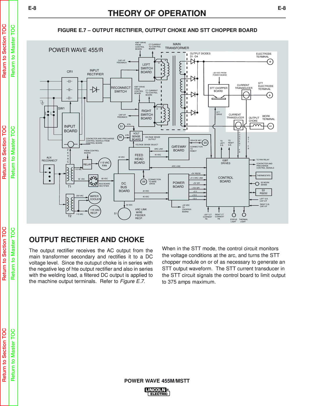
FIGURE E.7 – OUTPUT RECTIFIER, OUTPUT CHOKE AND STT CHOPPER BOARD


IGBT DRIVE

CT CURRENT

MAIN


FROM


POWER WAVE 455/R

CONTROL

TO CONTROL

TRANSFORMER


BOARD

BOARD


OUTPUT DIODES

ELECTRODE


D1 -D4

TERMINAL


CAP. V/F


+


FEEDBACK


LEFT


CR1

INPUT

SWITCH


BOARD


+20 VDC FROM

RECTIFIER


POWER BOARD


CURRENT

STT

RECONNECT

IGBT DRIVE


ELECTRODE


STT CHOPPER

TRANSDUCER

FROM


TERMINAL

SWITCH

CT CURRENT

BOARD


CONTROL


TO CONTROL


BOARD


+


BOARD


SW1

RIGHT


STT


SWITCH

CURRENT


CAP. V/F

DRIVE


WORK

FEEDBACK

BOARD

TRANSDUCER

OUTPUT


TERMINAL


CHOKE


INPUT


67A


S1


BOARD


VOLT


C


67B


U


SENSE


CONTACTOR AND PRECHARGE

S6

VOLTAGE SENSE


R

S


BOARD


OUTPUT


DEVICE NET


TO

R

T


CONTROL SIGNALS FROM


TO

E

T


CONTROL BOARD


S5

LEFT

RIGHT

N


VOLTAGE SENSE SELECT


GATEWAY

CONNECTION

S.B.

S.B.

T

F


2


FROM CONTROL


ARC LINK

BOARD

TO


F

B


ROBOT


4


BOARD


FEED

40 VDC


B


V


AUX

A


40 VDC

HEAD


TO FAN RELAY


IGBT


RECONNECT

C


115 VAC


BOARD


DRIVES


CONTACTOR AND


RELAY

FAN


ARC LINK


PRECHARGE


115 VAC


CONTROL SIGNALS


+5V RS232


52 VAC


65 VDC


CONNECTION


+5 V ARC LINK

CONTROL


THERMOSTATS


BOARD


BUS BOARD


DC

S6 TO WIRE

POWER


+5V SPI


S2 WORK


T1


DRIVE


SENSE


RECTIFIER


BUS


BOARD

+15V SPI


BOARD


40 VDC


+5 V


S3


230 VAC


WATER


40 VDC


+15 V


RS232


-15 V


LEFT S.B.


COOLER


CAP. V/F


40 VDC


+20 VDC


RIGHT S.B.


CAP. V/F


ARC LINK


TO


115 VAC


CHOPPER


115 VAC


RECP.


S1


WIRE


BOARD

LEFT CT

RIGHT CT


FEEDER


T2


CURRENT

CURRENT


RECP.


FB

FB


STATUS

THERMAL


LIGHT


LIGHT

OUTPUT RECTIFIER AND CHOKE

The output rectifier receives the AC output from the

When in the STT mode, the control circuit monitors

the voltage conditions at the arc, and turns the STT

main transformer secondary and rectifies it to a DC

voltage level. Since the outuput choke is in series with

chopper module on or of as necessary to generate an

the negative leg of hte output rectifier and also in series

STT output waveform. The STT current transducer in

with the welding load, a filtered DC output is applied to

the STT circuit signals the control board to limit output

the machine output terminals. Refer to Figure E.7.

to 375 amps maximum.

POWER WAVE 455M/MSTT

Page 42
Image 42
Lincoln Electric SVM173-A service manual Output Rectifier and Choke

SVM173-A specifications

The Lincoln Electric SVM173-A is a highly regarded welding power supply that stands out for its advanced features, robust performance, and innovative technologies. This machine is specifically designed to meet the demands of both industrial and commercial welding applications, making it a versatile choice for professionals.

One of the main features of the SVM173-A is its high efficiency, which contributes to reduced energy costs and enhanced productivity. The device operates on a powerful DC output, ensuring stable and reliable arc performance. This is particularly beneficial when working with various materials, allowing for smooth and consistent welds.

The SVM173-A leverages Lincoln Electric's proprietary inverter technology. This innovation allows for a lighter weight and more compact design without compromising on power. The inverter technology also enables precise control of the welding parameters, which is critical for maintaining quality across different welding tasks. Additionally, the machine features a wide input voltage range, accommodating various power sources and enhancing its adaptability on job sites.

Another key characteristic of the SVM173-A is its user-friendly interface. The machine is equipped with an intuitive control panel that allows users to easily adjust settings, making it accessible for both novice and experienced welders. The digital display provides clear readouts of output parameters and error notifications, facilitating quick troubleshooting in the field.

Safety is paramount in welding operations, and the SVM173-A incorporates several protection features. These include overcurrent protection, overheating protection, and circuit protection, ensuring that the machine operates safely and efficiently under various conditions.

The SVM173-A also supports a wide range of welding processes, including MIG, TIG, and stick welding. This flexibility makes it an ideal choice for workshops that require a multi-process machine capable of handling diverse applications. Furthermore, the SVM173-A supports spool gun operation, which is particularly useful for aluminum welding, enhancing its versatility even further.

In summary, the Lincoln Electric SVM173-A is a powerful and adaptable welding machine that combines innovative technologies, user-friendly features, and robust safety mechanisms. Its high efficiency, precision control, and multi-process capabilities make it an excellent investment for professionals seeking reliable performance in demanding environments. Whether for heavy-duty industrial use or more specialized applications, the SVM173-A stands as a testament to Lincoln Electric's commitment to quality and innovation in welding solutions.