MC-6 specifications
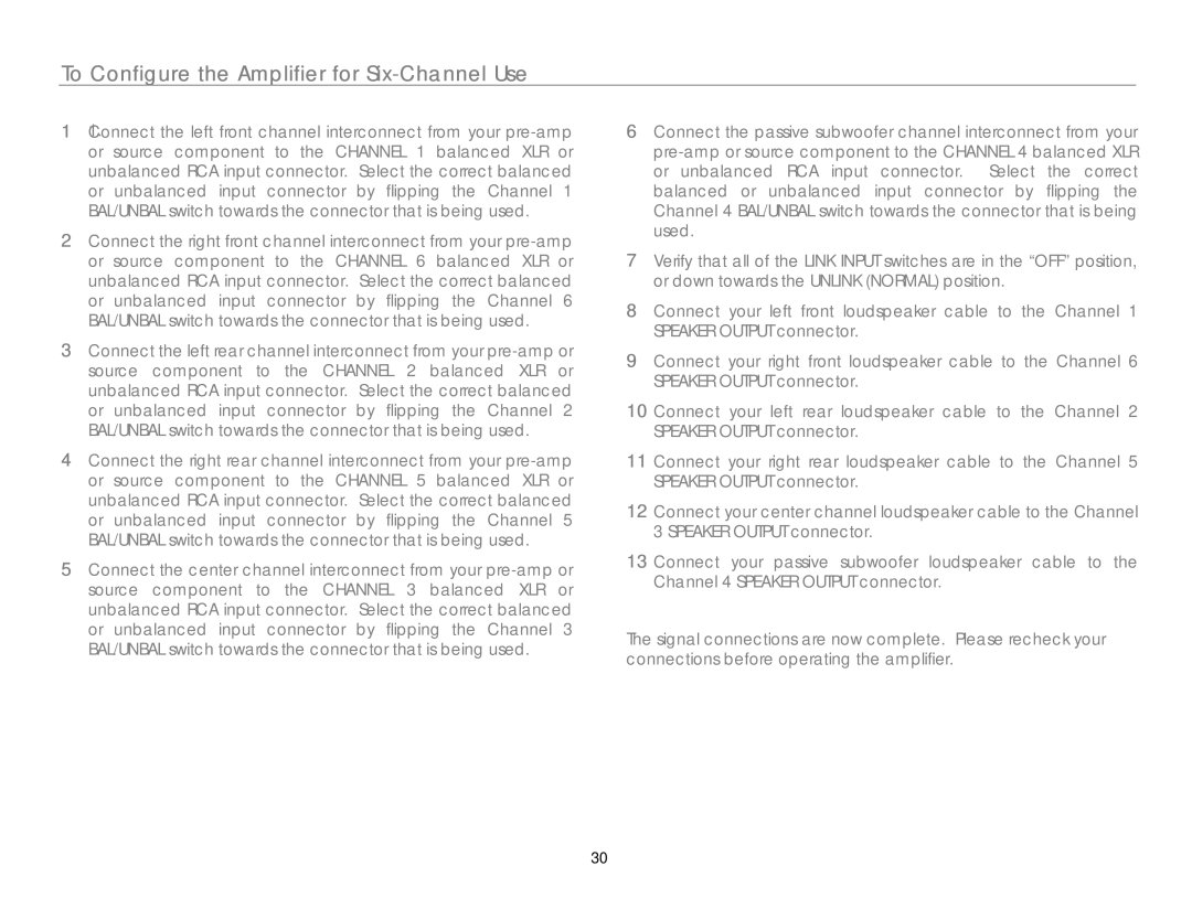
The Link electronic MC-6 is an advanced multi-channel sound system controller designed for musicians, sound engineers, and music producers who require high-quality sound management and versatile control in their audio setups. Known for its innovative features and robust performance, the MC-6 stands out as a vital tool in both live sound and studio environments.One of the principal features of the MC-6 is its ability to manage up to six audio channels simultaneously. This allows users to create custom mixes tailored to their specific needs, enabling precise control over each individual sound source. The user interface is designed for ease of use, with intuitive controls that allow for quick adjustments on-the-fly. This is a critical advantage during live performances where time is of the essence.
The MC-6 is equipped with cutting-edge digital signal processing technology. This feature enhances audio quality while providing tools for equalization, compression, and reverb. The onboard effects can significantly elevate the sound experience, offering flexibility in how audio is mixed and presented. Users can also store presets, which speeds up the setup process for recurring performances or recording sessions.
Another noteworthy characteristic of the MC-6 is its connectivity options. It supports a variety of input and output formats, including XLR, TRS, and USB connections, making it compatible with a wide range of industry-standard equipment. This versatility allows users to seamlessly integrate the MC-6 into any sound system configuration, whether in a club setting or a personal studio.
For added convenience, the MC-6 can also be controlled remotely through mobile devices or computers. This wireless capability is particularly valuable during live events, as it permits the sound engineer to make real-time adjustments from different locations in the venue. The connectivity also supports MIDI control, allowing the integration of external devices for enhanced sound manipulation.
Overall, the Link electronic MC-6 combines cutting-edge technology with user-friendly features, making it an ideal solution for those seeking to elevate their audio experiences. With its multi-channel management, digital signal processing, versatile connectivity, and remote control capabilities, the MC-6 is sure to meet the demands of any professional audio environment. This tool is poised to be a game-changer for anyone looking to refine their sound and enhance their overall audio production.
