Nortel Networks 450 manual Vlan Port Configuration, FieldDescription

Models: 450

1 290
Download 290 pages 47.47 Kb
Page 158
Image 158

Using the BayStack 450 10/100/1000 Series Switch

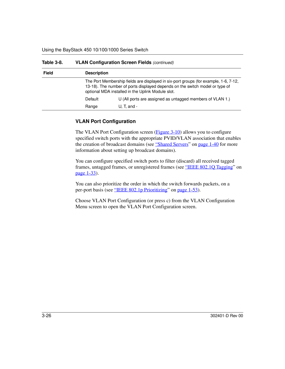
Table 3-8. VLAN Configuration Screen Fields (continued)

FieldDescription

The Port Membership fields are displayed in six-port groups (for example, 1-6, 7-12, 13-18). The number of ports displayed depends on the switch model or type of optional MDA installed in the Uplink Module slot.

Default

U (All ports are assigned as untagged members of VLAN 1.)

Range

U, T, and -


VLAN Port Configuration

The VLAN Port Configuration screen (Figure 3-10) allows you to configure specified switch ports with the appropriate PVID/VLAN association that enables the creation of broadcast domains (see “ Shared Servers” on page 1-40 for more information about setting up broadcast domains).

You can configure specified switch ports to filter (discard) all received tagged frames, untagged frames, or unregistered frames (see “ IEEE 802.1Q Tagging” on page 1-33).

You can also prioritize the order in which the switch forwards packets, on a per-port basis (see “ IEEE 802.1p Prioritizing” on page 1-53).

Choose VLAN Port Configuration (or press c) from the VLAN Configuration Menu screen to open the VLAN Port Configuration screen.
3-26

302401-D Rev 00

Page 158
Image 158
Nortel Networks 450 manual Vlan Port Configuration, FieldDescription