Using the BayStack 450 10/100/1000 Series Switch
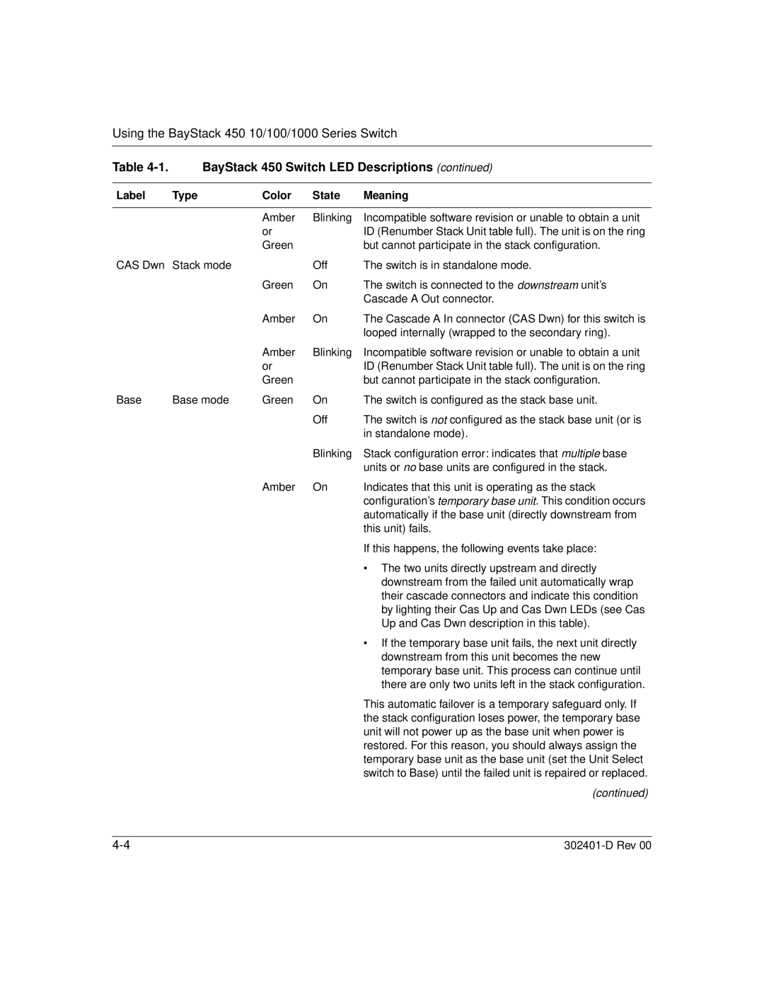
Table | BayStack 450 Switch LED Descriptions (continued) | |||
|
|
|
|
|
Label | Type | Color | State | Meaning |
|
|
|
|
|
|
| Amber | Blinking | Incompatible software revision or unable to obtain a unit |
|
| or |
| ID (Renumber Stack Unit table full). The unit is on the ring |
|
| Green |
| but cannot participate in the stack configuration. |
CAS Dwn | Stack mode |
| Off | The switch is in standalone mode. |
|
| Green | On | The switch is connected to the downstream unit’s |
|
|
|
| Cascade A Out connector. |
|
| Amber | On | The Cascade A In connector (CAS Dwn) for this switch is |
|
|
|
| looped internally (wrapped to the secondary ring). |
|
| Amber | Blinking | Incompatible software revision or unable to obtain a unit |
|
| or |
| ID (Renumber Stack Unit table full). The unit is on the ring |
|
| Green |
| but cannot participate in the stack configuration. |
Base | Base mode | Green | On | The switch is configured as the stack base unit. |
|
|
| Off | The switch is not configured as the stack base unit (or is |
|
|
|
| in standalone mode). |
|
|
| Blinking | Stack configuration error: indicates that multiple base |
|
|
|
| units or no base units are configured in the stack. |
|
| Amber | On | Indicates that this unit is operating as the stack |
|
|
|
| configuration’s temporary base unit. This condition occurs |
automatically if the base unit (directly downstream from this unit) fails.
If this happens, the following events take place:
• The two units directly upstream and directly downstream from the failed unit automatically wrap their cascade connectors and indicate this condition by lighting their Cas Up and Cas Dwn LEDs (see Cas Up and Cas Dwn description in this table).
• If the temporary base unit fails, the next unit directly downstream from this unit becomes the new temporary base unit. This process can continue until there are only two units left in the stack configuration.
This automatic failover is a temporary safeguard only. If the stack configuration loses power, the temporary base unit will not power up as the base unit when power is restored. For this reason, you should always assign the temporary base unit as the base unit (set the Unit Select switch to Base) until the failed unit is repaired or replaced.
(continued)