Using the Console Interface
Screen Fields and Descriptions
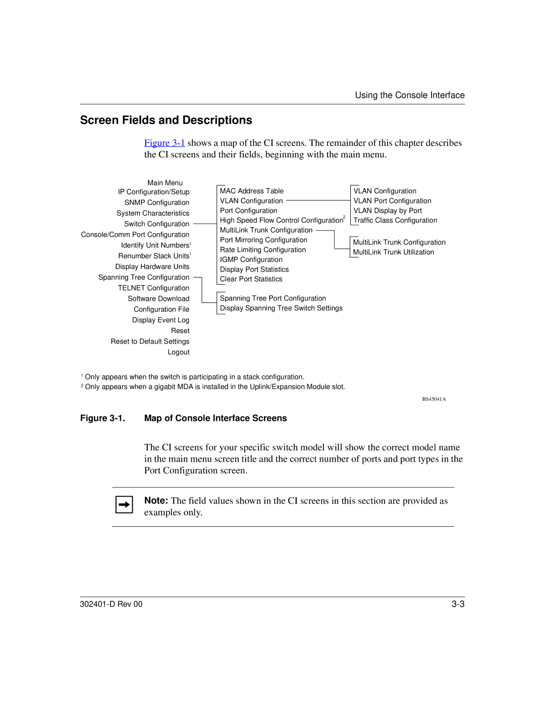
Figure 3-1 shows a map of the CI screens. The remainder of this chapter describes the CI screens and their fields, beginning with the main menu.
Main Menu
IP Configuration/Setup
SNMP Configuration
System Characteristics
Switch Configuration
Console/Comm Port Configuration Identify Unit Numbers1 Renumber Stack Units1 Display Hardware Units Spanning Tree Configuration TELNET Configuration Software Download Configuration File Display Event Log Reset Reset to Default Settings Logout
MAC Address Table
VLAN Configuration
Port Configuration
High Speed Flow Control Configuration2
MultiLink Trunk Configuration
Port Mirroring Configuration
Rate Limiting Configuration
IGMP Configuration
Display Port Statistics
Clear Port Statistics
Spanning Tree Port Configuration Display Spanning Tree Switch Settings
VLAN Configuration VLAN Port Configuration VLAN Display by Port Traffic Class Configuration
MultiLink Trunk Configuration MultiLink Trunk Utilization
1Only appears when the switch is participating in a stack configuration.
2Only appears when a gigabit MDA is installed in the Uplink/Expansion Module slot.
BS45041A
Figure 3-1. Map of Console Interface Screens
The CI screens for your specific switch model will show the correct model name in the main menu screen title and the correct number of ports and port types in the Port Configuration screen.
Note: The field values shown in the CI screens in this section are provided as examples only.
|
