BayStack 450 10/100/1000 Series Switches
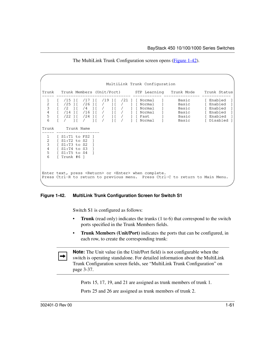
The MultiLink Trunk Configuration screen opens (Figure 1-42).
MultiLink Trunk Configuration |
| |
Trunk Trunk Members (Unit/Port) | STP Learning Trunk Mode | Trunk Status |
1 | [ | /15 ][ | /17 ][ | /19 ][ | /21 | ] [ Normal | ] | Basic | [ Enabled | ] | |||
2 | [ | /25 ][ | /26 ][ | / | ][ | / | ] [ Normal | ] | Basic | [ Enabled | ] | ||
3 | [ | /2 | ][ | /4 | ][ | / | ][ | / | ] [ Normal | ] | Basic | [ Enabled | ] |
4 | [ | /14 ][ | /16 ][ | / | ][ | / | ] [ Normal | ] | Basic | [ Enabled | ] | ||
5 | [ | /22 ][ | /24 ][ | / | ][ | / | ] [ Fast | ] | Basic | [ Enabled | ] | ||
6 | [ | / | ][ | / | ][ | / | ][ | / | ] [ Normal | ] | Basic | [ Disabled ] | |
Trunk |
| Trunk Name |
|
|
|
|
|
|
|
|
| ||
-----
1 [ S1:T1 to FS2 ]
2 [ S1:T2 to S2 ]
3 [ S1:T3 to S2 ]
4 [ S1:T4 to S3 ]
5 [ S1:T5 to S4 ]
6 [ Trunk #6 ]
Enter text, press <Return> or <Enter> when complete.
Press
Figure 1-42. MultiLink Trunk Configuration Screen for Switch S1
Switch S1 is configured as follows:
•Trunk (read only) indicates the trunks (1 to 6) that correspond to the switch ports specified in the Trunk Members fields.
•Trunk Members (Unit/Port) indicates the ports that can be configured, in each row, to create the corresponding trunk:
Note: The Unit value (in the Unit/Port field) is not configurable when the switch is operating standalone. For detailed information about the MultiLink Trunk Configuration screen fields, see “MultiLink Trunk Configuration” on page
Ports 15, 17, 19, and 21 are assigned as trunk members of trunk 1.
Ports 25 and 26 are assigned as trunk members of trunk 2.
|
