Using the Console Interface
IGMP Configuration
The IGMP Configuration screen allows you to set your switch ports to optimize IP multicast packets in a bridged Ethernet environment (see “ IGMP Snooping” on page
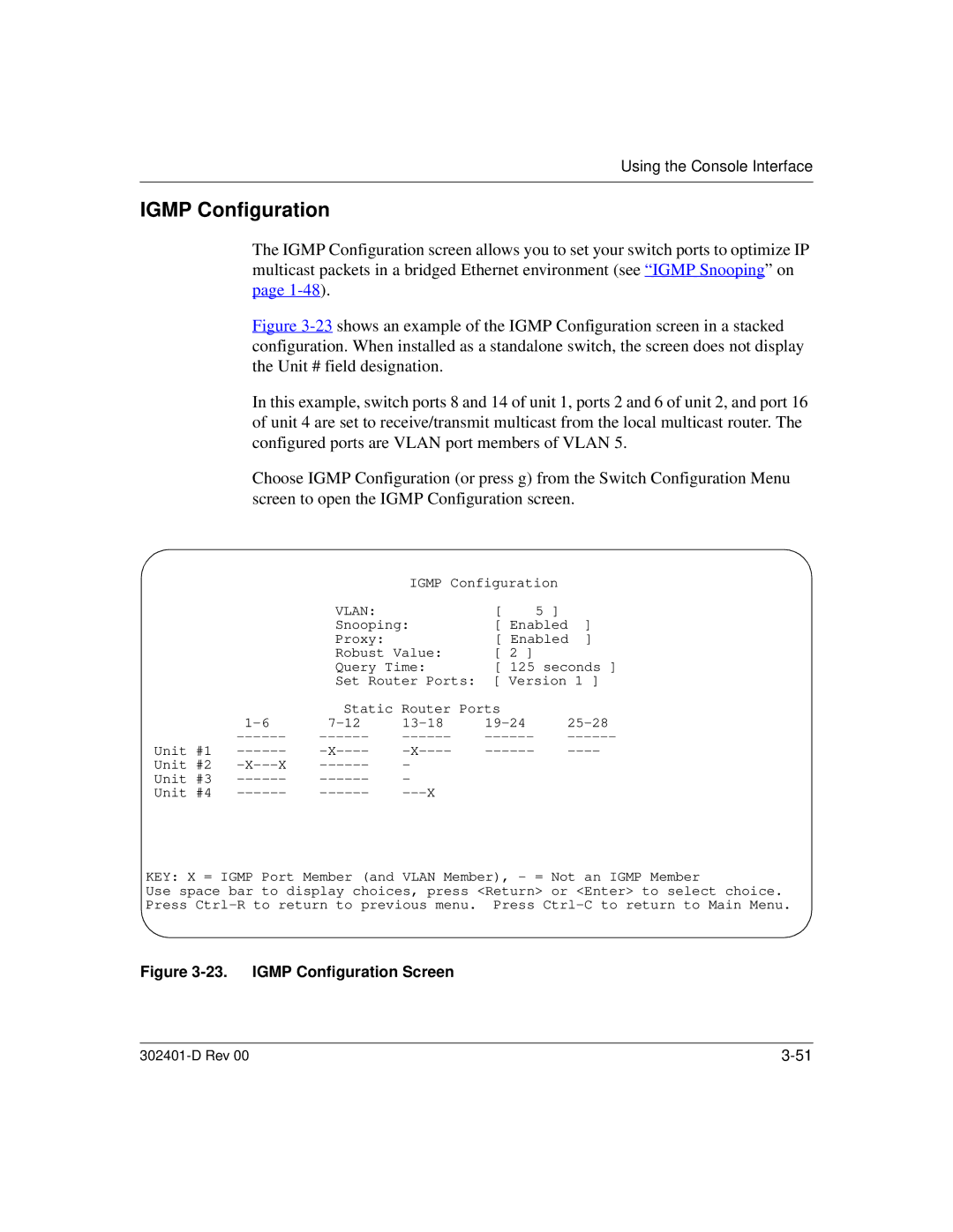
Figure 3-23 shows an example of the IGMP Configuration screen in a stacked configuration. When installed as a standalone switch, the screen does not display the Unit # field designation.
In this example, switch ports 8 and 14 of unit 1, ports 2 and 6 of unit 2, and port 16 of unit 4 are set to receive/transmit multicast from the local multicast router. The configured ports are VLAN port members of VLAN 5.
Choose IGMP Configuration (or press g) from the Switch Configuration Menu screen to open the IGMP Configuration screen.
|
|
| IGMP Configuration |
| ||
|
| VLAN: |
| [ | 5 ] |
|
|
| Snooping: | [ Enabled | ] | ||
|
| Proxy: |
| [ Enabled | ] | |
|
| Robust Value: | [ 2 ] |
|
| |
|
| Query Time: | [ 125 seconds ] | |||
|
| Set Router Ports: [ Version 1 ] | ||||
|
| Static Router Ports |
|
| ||
| ||||||
| ||||||
Unit #1 | ||||||
Unit #2 | - |
|
|
| ||
Unit #3 | - |
|
|
| ||
Unit #4 |
|
|
| |||
KEY: X = IGMP Port Member (and VLAN Member), - = Not an IGMP Member
Use space bar to display choices, press <Return> or <Enter> to select choice. Press
Figure 3-23. IGMP Configuration Screen
|