BayStack 450 10/100/1000 Series Switches
1
Unit 1 |
In |
2
1 = Base unit
2 = Last unit
O ut
3
Unit 2
Unit 3
Unit 4
Unit 5
Unit 6
Unit 7
Unit 8
4
3 = Cascade cable (PN
4 = Cascade
BS0034B
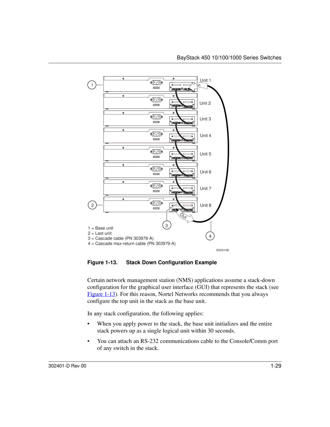
Figure 1-13. Stack Down Configuration Example
Certain network management station (NMS) applications assume a
In any stack configuration, the following applies:
•When you apply power to the stack, the base unit initializes and the entire stack powers up as a single logical unit within 30 seconds.
•You can attach an
|