Troubleshooting
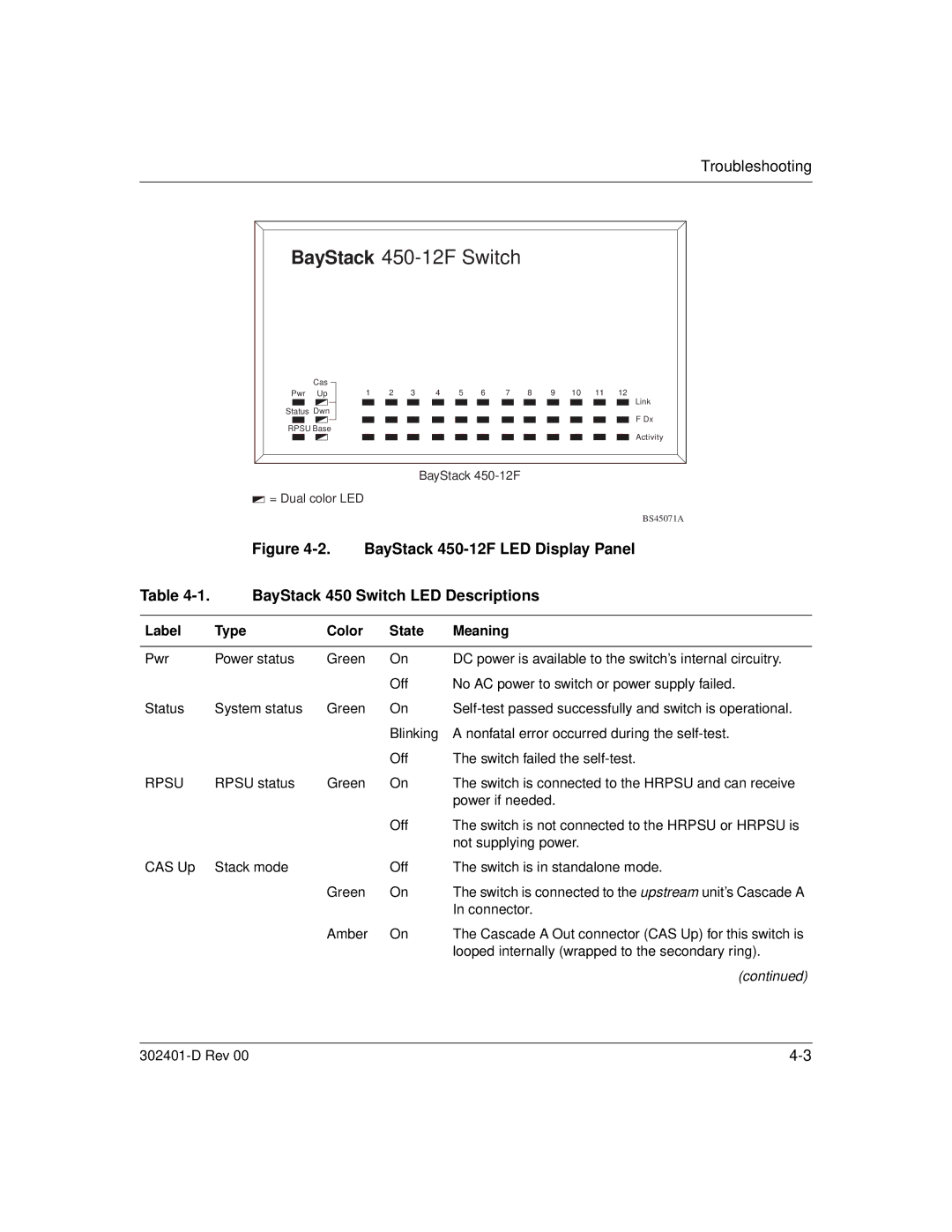
BayStack 450-12F Switch
Cas |
|
|
|
|
|
|
|
|
|
|
Pwr Up | 1 | 2 | 3 | 4 | 5 | 6 | 7 | 8 | 9 | 10 11 12 |
Link
Status Dwn
F Dx
RPSU Base
Activity
BayStack
![]() = Dual color LED
= Dual color LED
BS45071A
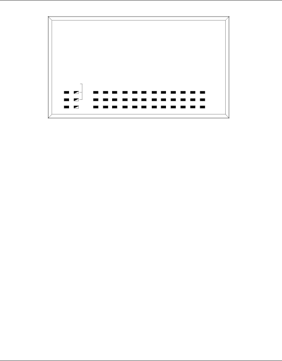
Figure 4-2. BayStack 450-12F LED Display Panel
Table | BayStack 450 Switch LED Descriptions | |||
|
|
|
|
|
Label | Type | Color | State | Meaning |
|
|
|
|
|
Pwr | Power status | Green | On | DC power is available to the switch’s internal circuitry. |
|
|
| Off | No AC power to switch or power supply failed. |
Status | System status | Green | On | |
|
|
| Blinking | A nonfatal error occurred during the |
|
|
| Off | The switch failed the |
RPSU | RPSU status | Green | On | The switch is connected to the HRPSU and can receive |
|
|
|
| power if needed. |
|
|
| Off | The switch is not connected to the HRPSU or HRPSU is |
|
|
|
| not supplying power. |
CAS Up | Stack mode |
| Off | The switch is in standalone mode. |
|
| Green | On | The switch is connected to the upstream unit’s Cascade A |
|
|
|
| In connector. |
|
| Amber | On | The Cascade A Out connector (CAS Up) for this switch is |
|
|
|
| looped internally (wrapped to the secondary ring). |
(continued)
|