Using the BayStack 450 10/100/1000 Series Switch
Verifying the Installation
When power is applied to the switch,
Verifying the Installation Using the LEDs
To verify the installation using the LEDs, check that the switch
Table 2-1. Power-Up Sequence
Stage Description | LED indication |
1Immediately after AC power is applied to the switch, DC power is available to the switch’s internal circuitry.
The Power LED turns on within 5 seconds (Figure
2 The switch initiates a
If a nonfatal error occurs during
If the switch fails the
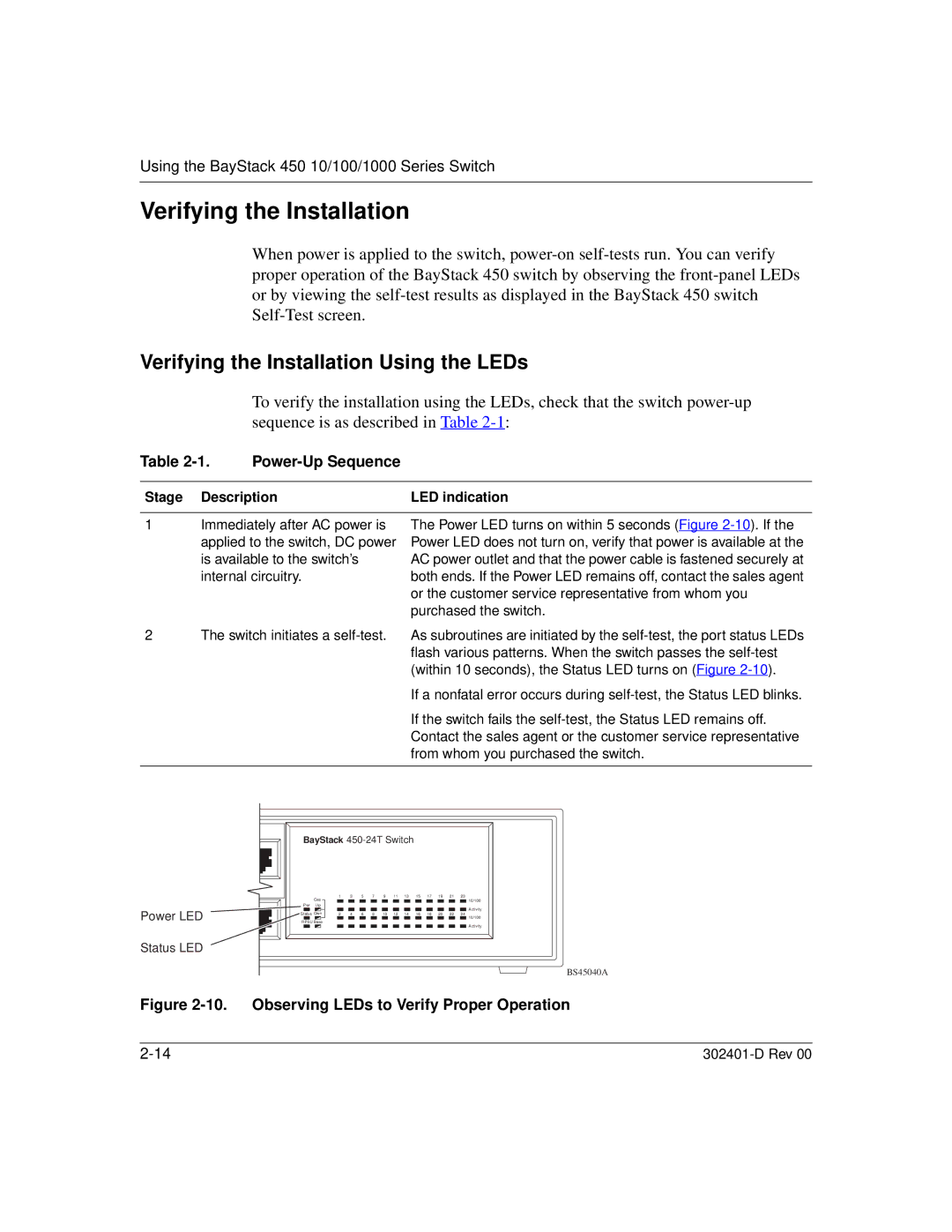
Power LED
Status LED
BayStack
|
| Cas | 1 |
| 3 |
| 5 |
| 7 |
| 9 |
| 11 | 13 |
| 15 |
| 17 |
| 19 |
| 21 |
| 23 |
| |
|
|
|
|
|
|
|
|
|
|
|
|
|
|
|
|
|
|
|
|
|
|
|
|
| 10/100 | |
Pwr Up |
|
|
|
|
|
|
|
|
|
|
|
|
|
|
|
|
|
|
|
|
|
|
| Activity | ||
|
|
|
|
|
|
|
|
|
|
|
|
|
|
|
|
|
|
|
|
|
|
|
|
|
|
|
Status Dwn | 2 |
| 4 |
| 6 |
| 8 |
| 10 |
| 12 | 14 |
| 16 |
| 18 |
| 20 |
| 22 |
| 24 | 10/100 | |||
|
|
|
|
|
|
|
|
|
|
|
|
|
|
|
|
|
|
|
|
|
|
|
|
|
| |
RPSU Base
Activity
BS45040A