Using the BayStack 450 10/100/1000 Series Switch
Front Panel
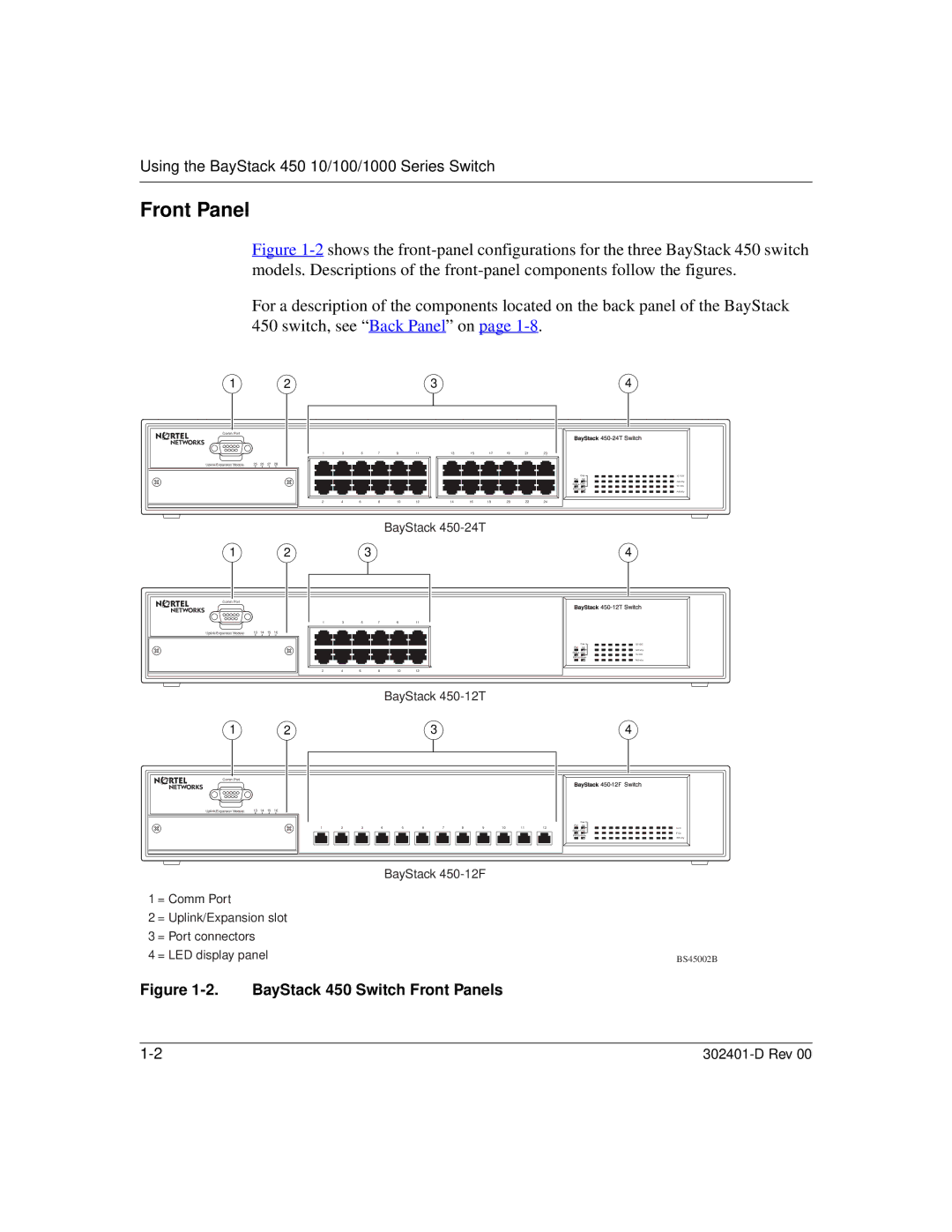
Figure 1-2 shows the front-panel configurations for the three BayStack 450 switch models. Descriptions of the front-panel components follow the figures.
For a description of the components located on the back panel of the BayStack 450 switch, see “ Back Panel” on page 1-8.
1 | 2 | 3 | 4 |
Comm Port
Uplink/Expansion Module | 25 26 27 28 |
1 2
Comm Port
Uplink/Expansion Module | 13 14 15 16 |
1 2
Comm Port |
|
Uplink/Expansion Module | 13 14 15 16 |
1 | 3 |
| 5 | 7 | 9 | 11 | 13 | 15 | 17 | 19 | 21 | 23 |
2 | 4 | 6 |
| 8 | 10 | 12 | 14 | 16 | 18 | 20 | 22 | 24 |
BayStack
3
1 | 3 |
| 5 | 7 | 9 | 11 |
2 | 4 | 6 |
| 8 | 10 | 12 |
BayStack
3
1 | 2 |
| 3 | 4 |
| 5 | 6 |
| 7 | 8 | 9 | 10 |
| 11 | 12 | |||||||
|
|
|
|
|
|
|
|
|
|
|
|
|
|
|
|
|
|
|
|
|
|
|
|
|
|
|
|
|
|
|
|
|
|
|
|
|
|
|
|
|
|
|
|
|
|
Cas | 10/100 |
Pwr Up
Activity
Status Dwn
10/100
RPSU Base
Activity
4
Cas | 10/100 |
Pwr Up
Activity
Status Dwn
10/100
RPSU Base
Activity
4
Cas
Pwr Up
Link
Status Dwn
F Dx
RPSU Base
Activity
|
| BayStack |
1 | = Comm Port |
|
2 | = Uplink/Expansion slot |
|
3 | = Port connectors |
|
4 | = LED display panel | BS45002B |