Using the BayStack 450 10/100/1000 Series Switch
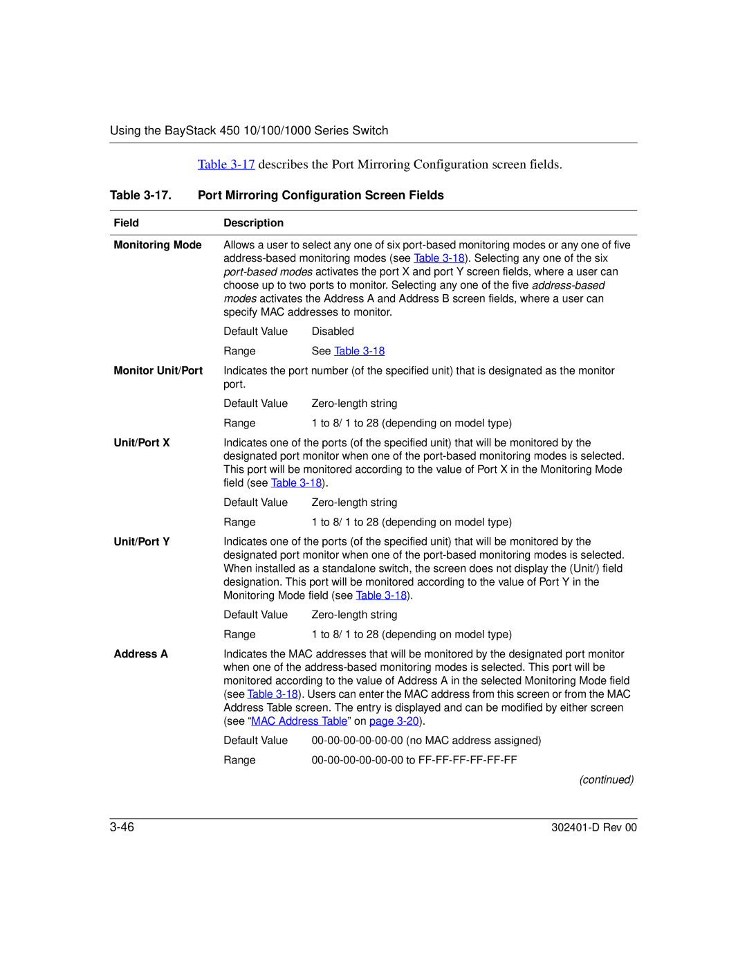
Table 3-17 describes the Port Mirroring Configuration screen fields.
Table | Port Mirroring Configuration Screen Fields | ||
|
|
|
|
Field |
| Description |
|
|
| ||
Monitoring Mode | Allows a user to select any one of six | ||
|
| ||
|
| ||
|
| choose up to two ports to monitor. Selecting any one of the five | |
|
| modes activates the Address A and Address B screen fields, where a user can | |
|
| specify MAC addresses to monitor. | |
|
| Default Value | Disabled |
|
| Range | See Table |
Monitor Unit/Port | Indicates the port number (of the specified unit) that is designated as the monitor | ||
|
| port. |
|
|
| Default Value | |
|
| Range | 1 to 8/ 1 to 28 (depending on model type) |
Unit/Port X |
| Indicates one of the ports (of the specified unit) that will be monitored by the | |
|
| designated port monitor when one of the | |
|
| This port will be monitored according to the value of Port X in the Monitoring Mode | |
|
| field (see Table | |
|
| Default Value | |
|
| Range | 1 to 8/ 1 to 28 (depending on model type) |
Unit/Port Y |
| Indicates one of the ports (of the specified unit) that will be monitored by the | |
|
| designated port monitor when one of the | |
|
| When installed as a standalone switch, the screen does not display the (Unit/) field | |
|
| designation. This port will be monitored according to the value of Port Y in the | |
|
| Monitoring Mode field (see Table | |
|
| Default Value | |
|
| Range | 1 to 8/ 1 to 28 (depending on model type) |
Address A |
| Indicates the MAC addresses that will be monitored by the designated port monitor | |
|
| when one of the | |
|
| monitored according to the value of Address A in the selected Monitoring Mode field | |
|
| (see Table | |
|
| Address Table screen. The entry is displayed and can be modified by either screen | |
|
| (see “MAC Address Table” on page | |
|
| Default Value | |
|
| Range | |
|
|
| (continued) |
