Using the BayStack 450 10/100/1000 Series Switch
Note: If you are replacing an installed MDA with another type of MDA, see
“ Replacing an MDA with a Different Model” on
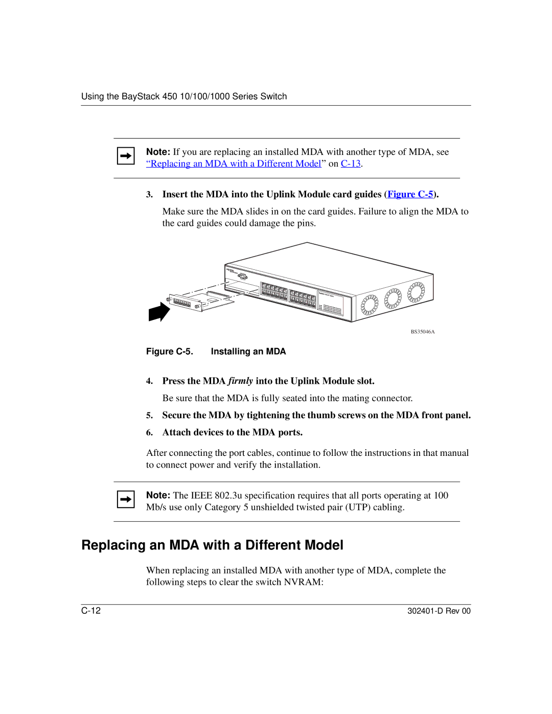
3.Insert the MDA into the Uplink Module card guides (Figure
Make sure the MDA slides in on the card guides. Failure to align the MDA to the card guides could damage the pins.
BS35046A
Figure C-5. Installing an MDA
4.Press the MDA firmly into the Uplink Module slot.
Be sure that the MDA is fully seated into the mating connector.
5.Secure the MDA by tightening the thumb screws on the MDA front panel.
6.Attach devices to the MDA ports.
After connecting the port cables, continue to follow the instructions in that manual to connect power and verify the installation.
Note: The IEEE 802.3u specification requires that all ports operating at 100 Mb/s use only Category 5 unshielded twisted pair (UTP) cabling.
Replacing an MDA with a Different Model
When replacing an installed MDA with another type of MDA, complete the following steps to clear the switch NVRAM: