Using the BayStack 450 10/100/1000 Series Switch
Table
| 62.5 Micron |
| 50 Micron |
|
|
Parameter | Multimode Fiber | Multimode Fiber | Units | ||
|
|
|
|
|
|
Modal bandwidth as measured at 850 nm | 160 | 200 | 400 | 500 | MHz · km |
(minimum, overfilled launch) |
|
|
|
|
|
Link power budget | 7.5 | 7.5 | 7.5 | 7.5 | dB |
Operating distance | 220 | 275 | 500 | 550 | m |
Channel insertion loss 1, 2 | 2.38 | 2.60 | 3.37 | 3.56 | dB |
Link power penalties | 4.27 | 4.29 | 4.07 | 3.57 | dB |
Unallocated margin in link power budget | 0.84 | 0.60 | 0.05 | 0.37 | dB |
|
|
|
|
|
|
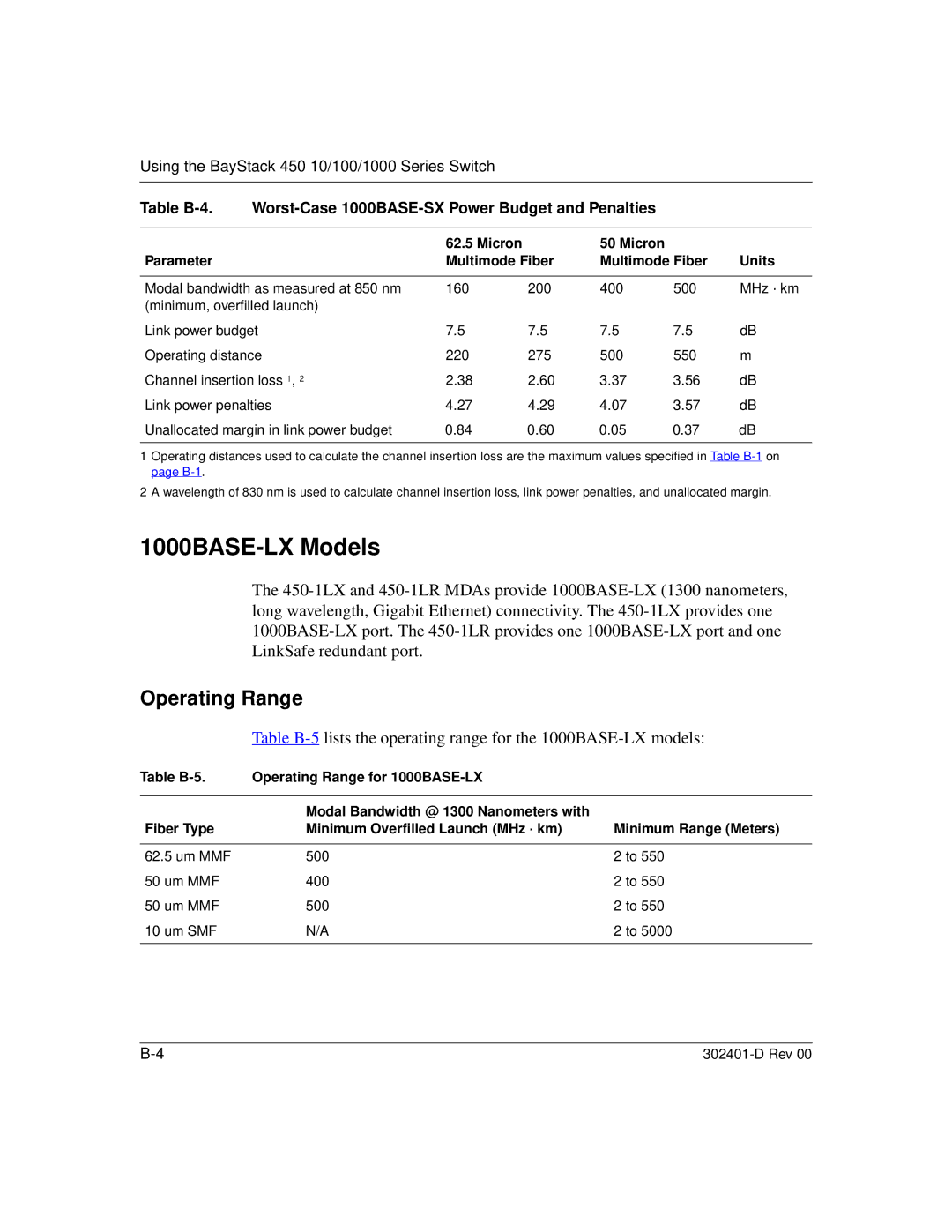
1 Operating distances used to calculate the channel insertion loss are the maximum values specified in Table
2 A wavelength of 830 nm is used to calculate channel insertion loss, link power penalties, and unallocated margin.
1000BASE-LX Models
The
Operating Range
Table
Table | Operating Range for |
|
|
|
|
| Modal Bandwidth @ 1300 Nanometers with |
|
Fiber Type | Minimum Overfilled Launch (MHz · km) | Minimum Range (Meters) |
|
|
|
62.5 um MMF | 500 | 2 to 550 |
50 um MMF | 400 | 2 to 550 |
50 um MMF | 500 | 2 to 550 |
10 um SMF | N/A | 2 to 5000 |
|
|
|
