Service Manual
3Troubleshooting (continued)
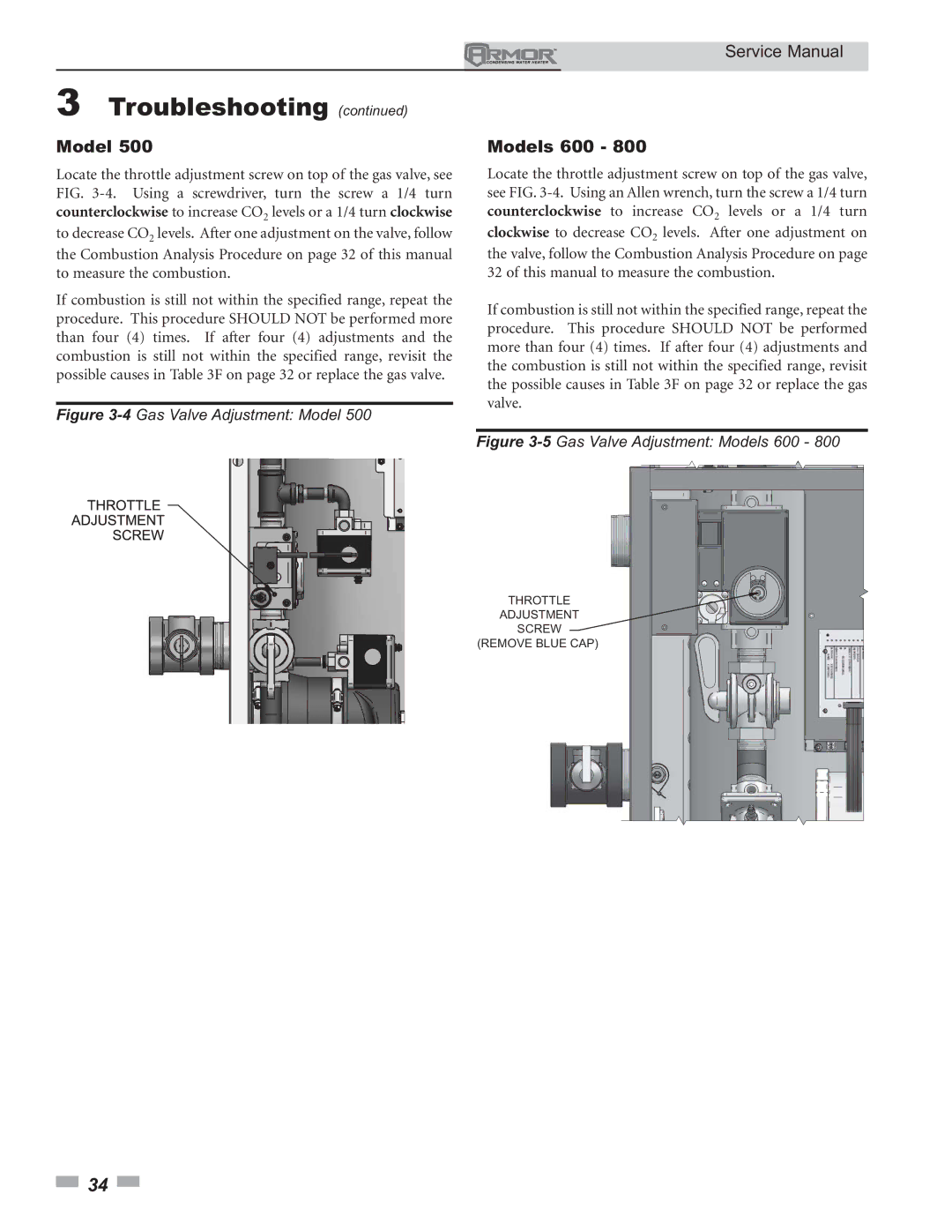
Model 500
Locate the throttle adjustment screw on top of the gas valve, see FIG.
If combustion is still not within the specified range, repeat the procedure. This procedure SHOULD NOT be performed more than four (4) times. If after four (4) adjustments and the combustion is still not within the specified range, revisit the possible causes in Table 3F on page 32 or replace the gas valve.
Figure 3-4 Gas Valve Adjustment: Model 500
Models 600 - 800
Locate the throttle adjustment screw on top of the gas valve, see FIG.
If combustion is still not within the specified range, repeat the procedure. This procedure SHOULD NOT be performed more than four (4) times. If after four (4) adjustments and the combustion is still not within the specified range, revisit the possible causes in Table 3F on page 32 or replace the gas valve.
Figure 3-5 Gas Valve Adjustment: Models 600 - 800
THROTTLE
ADJUSTMENT
SCREW
(REMOVE BLUE CAP)
![]() 34
34 ![]()