Precision Cooling
For Business-Critical Continuity™
Installation, Operation and Maintenance Manual - 50 & 60Hz


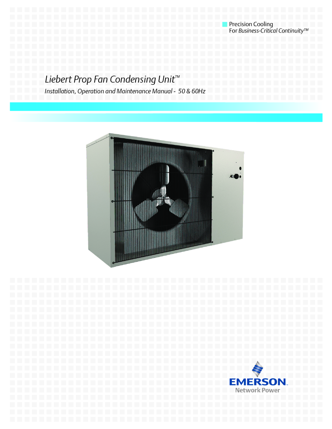
 Liebert Prop Fan Condensing Unit™