Installation
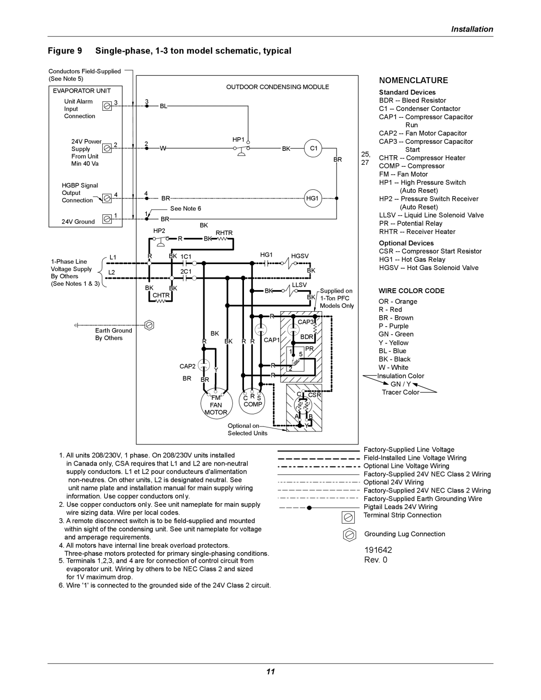
Figure 9 Single-phase, 1-3 ton model schematic, typical
Conductors
(See Note 5)
EVAPORATOR UNIT
Unit Alarm | 3 | |
Input |
| |
Connection |
| |
24V Power | 2 | |
Supply | ||
| ||
From Unit |
| |
Min 40 Va |
|
HGBP Signal
Output4
Connection
1
24V Ground
L1 | ||
| ||
Voltage Supply | L2 | |
By Others | ||
| ||
(See Notes 1 & 3) |
|
Earth Ground
By Others
|
|
| OUTDOOR CONDENSING MODULE | |||||||
3 | BL |
|
|
|
|
|
|
|
|
|
|
|
|
|
|
|
|
|
|
| |
2 |
|
|
| HP1 |
|
|
|
|
|
|
W |
|
|
|
| BK |
|
| C1 |
| |
|
|
|
|
|
|
|
| |||
|
|
|
|
|
|
|
|
|
| BR |
4 | BR |
|
|
|
|
|
|
| HG1 |
|
|
|
|
|
|
|
|
|
| ||
1 | See Note 6 |
|
|
|
|
|
|
|
| |
BR |
|
|
|
|
|
|
|
|
| |
| BK |
|
|
|
|
|
|
|
| |
| HP2 |
|
|
|
|
|
|
|
| |
| RHTR |
|
|
|
|
|
|
| ||
| R | BK |
|
|
|
|
|
|
|
|
R | BK 1C1 |
|
| HG1 |
| HGSV |
| |||
| 2C1 |
|
|
|
|
|
|
| BK |
|
BK | BK |
|
|
| BK |
| LLSV | Supplied on | ||
|
|
|
|
|
|
| ||||
CHTR |
|
|
|
|
|
| BK | |||
|
|
|
|
|
|
| ||||
|
|
|
|
|
|
|
|
|
| Models Only |
|
|
|
|
| R |
|
| CAP3 |
| |
|
|
|
|
|
|
|
|
| ||
|
| BK |
|
| CAP1 |
|
| BDR |
| |
|
| R | BK | R R |
|
|
| |||
|
|
|
|
| PR |
| ||||
|
|
|
|
|
| 1 | 5 |
| ||
|
|
|
|
|
|
|
| |||
|
|
|
|
|
|
|
|
|
| |
| CAP2 | Y |
|
| R | 2 |
|
|
| |
|
|
|
| R |
|
|
| |||
| BR | BR |
|
|
|
|
|
|
| |
|
|
|
|
|
|
|
|
| ||
|
| 'FM' |
| C R S |
|
|
| C | CSR | |
|
| FAN |
| COMP |
|
|
|
|
|
|
|
| MOTOR |
|
|
|
| A | B |
| |
|
|
|
|
|
|
|
|
| ||
|
|
| Optional on |
|
|
|
| Y |
| |
|
|
| Selected Units |
|
|
|
|
| ||
NOMENCLATURE
Standard Devices
BDR
C1
CAP1
Run
CAP2
CAP3
25, | Start | ||||
CHTR | |||||
27 | |||||
COMP | |||||
|
| ||||
|
| FM | |||
|
| HP1 | |||
|
| (Auto Reset) | |||
|
| HP2 | |||
|
| (Auto Reset) | |||
|
| LLSV | |||
|
| PR | |||
|
| RHTR | |||
|
| Optional Devices | |||
|
| CSR | |||
|
| HG1 | |||
|
| HGSV | |||
|
| WIRE COLOR CODE | |||
|
| OR - Orange | |||
|
| R - Red | |||
|
| BR - Brown | |||
|
| P - Purple | |||
|
| GN - Green | |||
|
| Y - Yellow | |||
|
| BL - Blue | |||
|
| BK - Black | |||
|
| W - White | |||
|
| Insulation Color | |||
|
| ||||
|
| GN / Y | |||
|
| Tracer Color |
|
| |
|
|
| |||
1.All units 208/230V, 1 phase. On 208/230V units installed
in Canada only, CSA requires that L1 and L2 are
2.Use copper conductors only. See unit nameplate for main supply wire sizing data. Wire per local codes.
3.A remote disconnect switch is to be
4.All motors have internal line break overload protectors.
5.Terminals 1,2,3, and 4 are for connection of control circuit from evaporator unit. Wiring by others to be NEC Class 2 and sized for 1V maximum drop.
6.Wire '1' is connected to the grounded side of the 24V Class 2 circuit.
Optional Line Voltage Wiring
Optional 24V Wiring
Pigtail Leads 24V Wiring
Terminal Strip Connection
Grounding Lug Connection
191642 Rev. 0
11