Installation
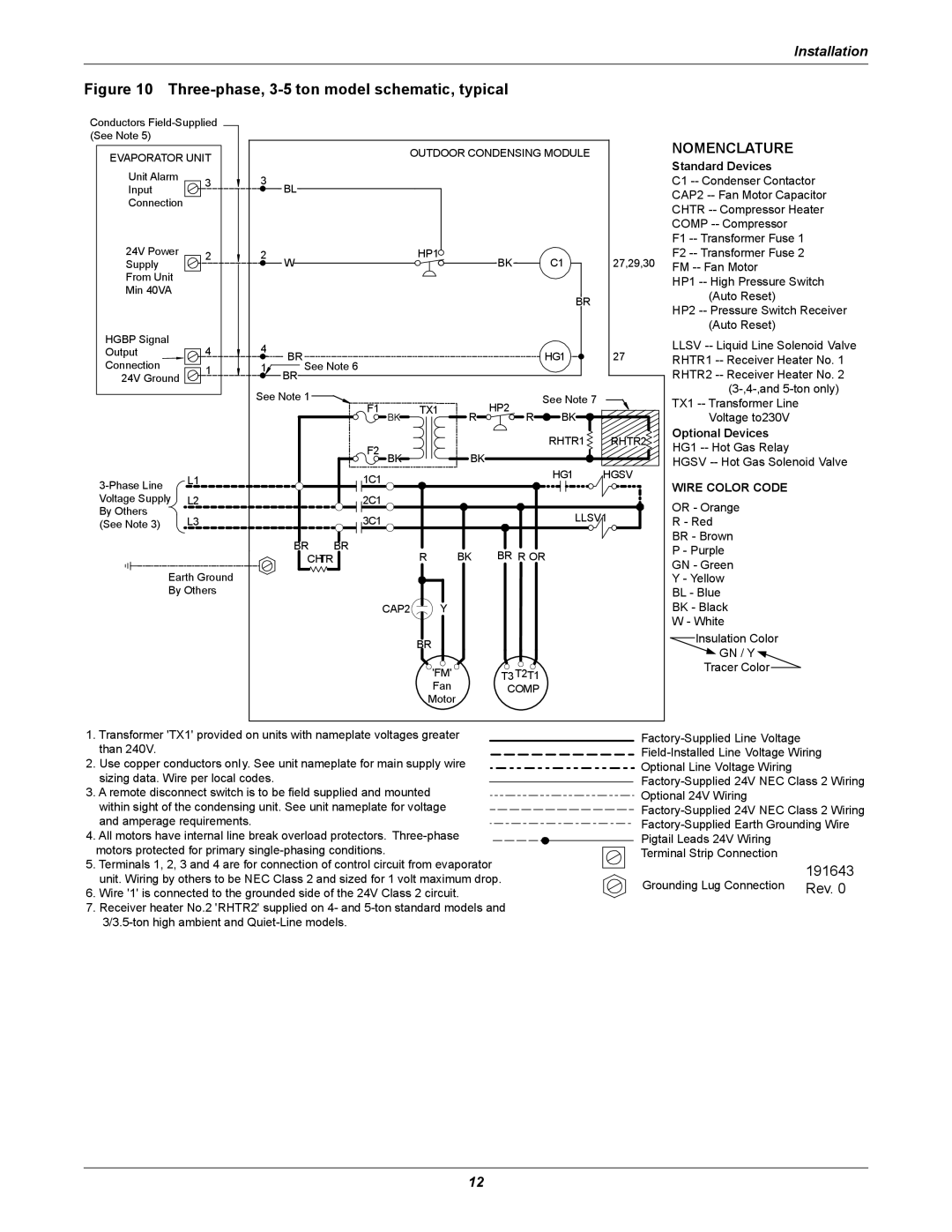
Figure 10 Three-phase, 3-5 ton model schematic, typical
Conductors
(See Note 5)
EVAPORATOR UNIT |
|
|
| OUTDOOR CONDENSING MODULE |
| |||||
|
|
|
|
|
|
|
|
| ||
Unit Alarm | 3 | 3 | BL |
|
|
|
|
|
|
|
Input |
|
|
|
|
|
|
| |||
|
|
|
|
|
|
|
|
| ||
Connection |
|
|
|
|
|
|
|
|
|
|
24V Power | 2 | 2 | W |
|
| HP1 |
| BK | C1 | 27,29,30 |
Supply |
|
|
|
|
|
| ||||
From Unit |
|
|
|
|
|
|
|
|
|
|
Min 40VA |
|
|
|
|
|
|
|
| BR |
|
|
|
|
|
|
|
|
|
|
| |
HGBP Signal | 4 | 4 |
|
|
|
|
|
|
|
|
Output | BR See Note 6 |
|
|
|
| HG1 | 27 | |||
Connection | 1 | 1 |
|
|
|
| ||||
24V Ground |
|
| BR |
|
|
|
|
|
|
|
|
| See Note 1 | F1 |
| TX1 |
| HP2 | See Note 7 |
| |
|
|
|
| BK | R | BK |
| |||
|
|
|
|
|
| R |
| |||
|
|
|
| F2 |
|
|
|
| RHTR1 | RHTR2 |
|
|
|
| BK |
| BK |
|
|
| |
L1 |
|
| 1C1 |
|
|
|
| HG1 | HGSV | |
|
|
|
|
|
|
|
| |||
|
|
|
|
|
|
|
|
|
| |
Voltage Supply | L2 |
|
| 2C1 |
|
|
|
|
|
|
By Others | L3 |
|
| 3C1 |
|
|
|
| LLSV1 | |
(See Note 3) |
|
|
|
|
|
| ||||
|
|
| BR | BR |
| R | BK | BR R OR |
| |
|
|
| CHTR |
|
|
| ||||
Earth Ground |
|
|
|
|
|
|
|
|
| |
By Others |
|
|
|
|
|
|
|
|
| |
|
|
|
|
| CAP2 | Y |
|
|
|
|
|
|
|
|
|
| BR |
|
|
|
|
|
|
|
|
|
| 'FM' |
| T3T2T1 |
|
|
|
|
|
|
|
| Fan |
| COMP |
|
|
|
|
|
|
|
| Motor |
|
|
|
|
NOMENCLATURE
Standard Devices
C1
CAP2
CHTR
COMP
F1
F2
FM
HP1
(Auto Reset)
HP2
(Auto Reset)
LLSV
RHTR1
RHTR2
TX1
Voltage to230V
Optional Devices
HG1
HGSV
WIRE COLOR CODE
OR - Orange
R - Red
BR - Brown
P - Purple
GN - Green
Y - Yellow
BL - Blue
BK - Black
W - White
Insulation Color
![]() GN / Y
GN / Y ![]()
Tracer Color
1.Transformer 'TX1' provided on units with nameplate voltages greater than 240V.
2.Use copper conductors only. See unit nameplate for main supply wire sizing data. Wire per local codes.
3.A remote disconnect switch is to be field supplied and mounted within sight of the condensing unit. See unit nameplate for voltage
and amperage requirements.
4. All motors have internal line break overload protectors.
5. Terminals 1, 2, 3 and 4 are for connection of control circuit from evaporator
unit. Wiring by others to be NEC Class 2 and sized for 1 volt maximum drop. 6. Wire '1' is connected to the grounded side of the 24V Class 2 circuit.
7.Receiver heater No.2 'RHTR2' supplied on 4- and
Optional Line Voltage Wiring
Optional 24V Wiring
Pigtail Leads 24V Wiring
Terminal Strip Connection
191643
Grounding Lug Connection Rev. 0
12