Installation
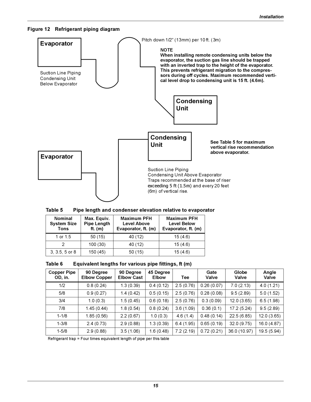
Figure 12 Refrigerant piping diagram
Evaporator
Suction Line Piping
Condensing Unit
Below Evaporator
Evaporator
Pitch down 1/2" (13mm) per 10 ft. (3m)
NOTE
When installing remote condensing units below the
NOTE
evaporator, the suction gas line should be trapped When installing remote condensing units elow the with an inverted trap to the height of the evaporator. evaporator, the suction gas line should be trapped with
This prevents refrigerant migration to the compres- an inverted trap to the height of the evaporator. This sors during off cycles. Maximum recommended verti- prevents refrigerant migration to the compressors
cal level drop to condensing unit is 15 ft. (4.6m). during off cycles . Maximum recommended vertical level drop to condensing unit is15 ft. (4.6m) .
Condensing
Unit
Condensing | See Table 5 for maximum | |
Unit | ||
vertical rise recommendation | ||
| above evaporator. | |
|
|
Suction Line Piping
Condensing Unit Above Evaporator Traps recommended at the base of riser exceeding 5 ft (1.5m) and every 20 feet (6m) of vertical rise.
Table 5 | Pipe length and condenser elevation relative to evaporator | ||||
Nominal |
| Max. Equiv. | Maximum PFH | Maximum PFH |
|
System Size | Pipe Length | Level Above | Level Below |
| |
Tons |
| ft. (m) | Evaporator, ft. (m) | Evaporator, ft. (m) |
|
1 or 1.5 |
| 50 (15) | 40 (12) | 15 (4.6) |
|
|
|
|
|
|
|
2 |
| 100 (30) | 40 (12) | 15 (4.6) |
|
|
|
|
|
| |
3, 3.5, 5 or 8 | 150 (45) | 50 (15) | 15 (4.6) |
| |
|
|
|
|
|
|
Table 6 | Equivalent lengths for various pipe fittings, ft (m) |
|
|
|
| |||||
|
|
|
|
|
|
|
| |||
Copper Pipe | 90 Degree | 90 Degree | 45 Degree |
| Gate | Globe | Angle | |||
OD, in. |
| Elbow Copper | Elbow Cast | Elbow | Tee | Valve | Valve | Valve | ||
1/2 |
| 0.8 (0.24) | 1.3 (0.39) | 0.4 (0.12) | 2.5 (0.76) | 0.26 (0.07) | 7.0 | (2.13) | 4.0 (1.21) | |
|
|
|
|
|
|
|
|
|
| |
5/8 |
| 0.9 (0.27) | 1.4 (0.42) | 0.5 (0.15) | 2.5 (0.76) | 0.28 (0.08) | 9.5 | (2.89) | 5.0 (1.52) | |
|
|
|
|
|
|
|
|
|
| |
3/4 |
| 1.0 | (0.3) | 1.5 (0.45) | 0.6 (0.18) | 2.5 (0.76) | 0.3 (0.09) | 12.0 (3.65) | 6.5 (1.98) | |
|
|
|
|
|
|
|
|
|
| |
7/8 |
| 1.45 | (0.44) | 1.8 (0.54) | 0.8 (0.24) | 3.6 (1.09) | 0.36 (0.1) | 17.2 (5.24) | 9.5 (2.89) | |
|
|
|
|
|
|
|
|
|
| |
| 1.85 | (0.56) | 2.2 (0.67) | 1.0 (0.3) | 4.6 (1.4) | 0.48 (0.14) | 22.5 (6.85) | 12.0 (3.65) | ||
|
|
|
|
|
|
|
|
| ||
| 2.4 (0.73) | 2.9 (0.88) | 1.3 (0.39) | 6.4 (1.95) | 0.65 (0.19) | 32.0 (9.75) | 16.0 (4.87) | |||
|
|
|
|
|
|
|
|
|
| |
| 2.9 (0.88) | 3.5 (1.06) | 1.6 (0.48) | 7.2 (2.19) | 0.72 (0.21) | 36.0 | (10.97) | 19.5 (5.94) | ||
|
|
|
|
|
|
|
|
|
|
|
Refrigerant trap = Four times equivalent length of pipe per this table
15