Contents
Liebert Prop Fan Condensing Unit
Example PFH037A-PL7
= 380/415-3ph-50Hz
Table of Contents
Figures
Prop Fan Condensing Units
Optional Equipment
Equipment Inspection
Location Considerations
Dimensional Data
Net Weight
Model Numbers Dimensional Data, in. mm Lb. kg 60Hz 50Hz
Cabinet and floor planning data, horizontal air discharge
Footprint Dimensions
Wall Mounting
Piping and Electrical Connections
Electrical and piping connections, horizontal air discharge
152
PFH096A- L
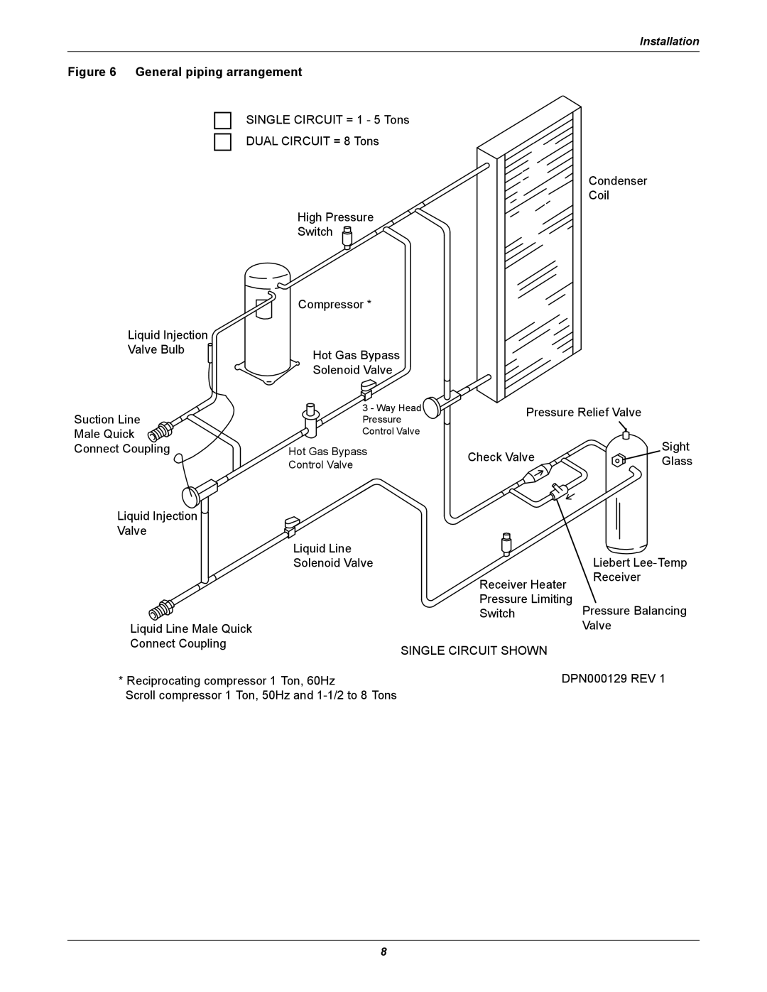
General piping arrangement
Electrical field connections, 1- to 5-ton units
Top Air Discharge Models
Electrical field connections, 8-ton units
Single-phase, 1-3 ton model schematic, typical
Three-phase, 3-5 ton model schematic, typical
Three-phase, 8 ton model schematic, typical
Piping Considerations
Piping for Elevation Differences between PFH and Evaporator
Evaporator
Condensing Unit
Equivalent lengths for various pipe fittings, ft m
Pre-Charged Line Sets
Field-Fabricated Line Sets
Refrigerant charge in Liebert pre-charged R-407C line sets
Line Size Length Charge R-407C Ft. m Lb-oz kg
Liebert PFH unit charge levels and coupling size
Recommended line sizes, OD Cu
Installation of Piping to Units
Piping connection sizes and torque
Line charges refrigerant per 100 ft m of Type L copper tube
Line Size OD Cu Coupling Size Torque, lb-ft. N-m
Filter Drier Selection and Installation
Install the New Condensing Unit
Remove Existing Condensing Unit
General System Charge Requirements
Evaporator Charge Levels
Evaporator Charge R-407C Indoor Unit Models Oz kg
Low-Voltage Control Wire Connections
Low-Voltage Control Wire Sizing
Electrical Connections
Nominal Input Voltage- Phase Capacity Electrical
Nominal Input Voltage-Phase Capacity Electrical
Electrical Data
Electrical data-High ambient models 105F/41C 60Hz
Electrical data-Quiet-Line models 95F/35C 60Hz
Electrical data-High ambient models 105F/41C 50Hz
Checklist for Completed Installation
Electrical data Quiet-Line models 95F/35C 50Hz
Compressor
High Head Pressure
Liebert Lee-Temp Flood Back Head Pressure Control
Adjustment
Hot Gas Bypass
Operation
Hot gas bypass diagram
General
Compressor Failure
Electrical Failure-Burnout
Mechanical Failure
Compressor Replacement
Field Charge Verification
Field verification charge
Model Numbers 407C 60 Hz 50 Hz Oz kg
Troubleshooting
Problem Cause Remedy
Single-Phase&Three-Phase UPS Environmental Systems
Web Site Monitoring
Uni
Etwo