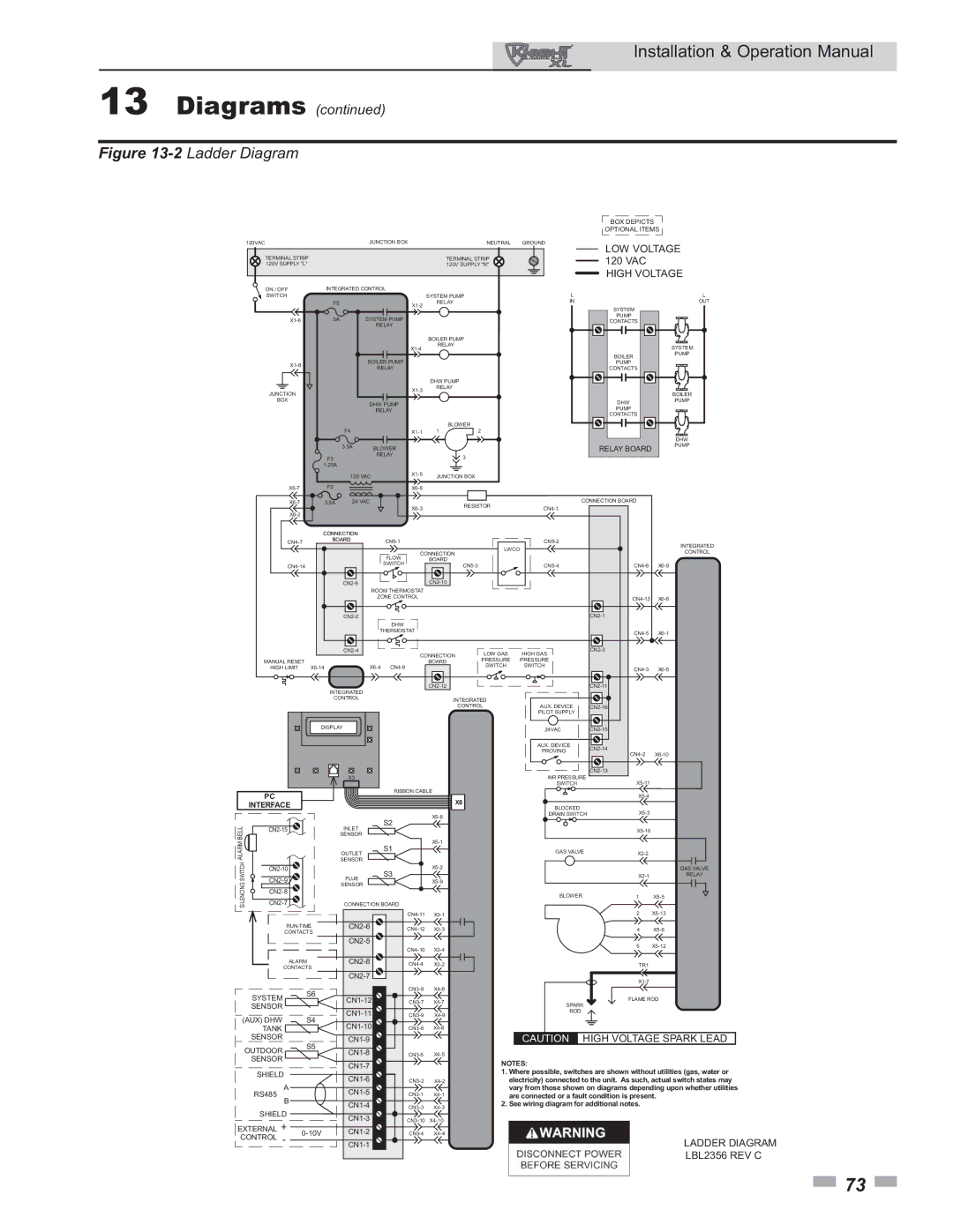
Lochinvar 800 operation manual 2Ladder Diagram

Models: 800

1 76
Download 76 pages 56.19 Kb
Page 73
Image 73

Installation & Operation Manual

13 Diagrams (continued)

Figure 13-2Ladder Diagram


BOX DEPICTS


OPTIONAL ITEMS

120VAC

JUNCTION BOX

NEUTRAL

GROUND


LOW VOLTAGE

TERMINAL STRIP


TERMINAL STRIP

120 VAC

120V SUPPLY "L"


120V SUPPLY "N"

HIGH VOLTAGE

ON / OFF

SWITCH

X1-6

X1-8

JUNCTION

BOX

X5-7

X6-7

X6-2

CN4-7

CN4-14

MANUAL RESET

HIGH LIMIT


PC

BELLALARM

INTERFACE

CN2-15


SWITCH

CN2-10

SILENCING

CN2-9

CN2-7


CN2-8

INTEGRATED CONTROL


L


L


SYSTEM PUMP


F5


X1-2

RELAY


IN

SYSTEM

OUT


5A


SYSTEM PUMP


PUMP


CONTACTS


RELAY


BOILER PUMP


X1-4

RELAY


SYSTEM


BOILER

PUMP


BOILER PUMP


PUMP


RELAY


CONTACTS


DHW PUMP


X1-3

RELAY


BOILER


DHW PUMP


DHW

PUMP


RELAY


PUMP


CONTACTS


BLOWER


F4


X1-1

1

2


DHW


3.5A

BLOWER


RELAY BOARD

PUMP

F3


RELAY


3


1.25A


120 VAC

X1-5

JUNCTION BOX


F2


X6-8


3.5A

24 VAC

X6-3

RESISTOR

CN4-1

CONNECTION BOARD


CONNECTION


BOARD

CN5-1


CN5-2


INTEGRATED


LWCO


CONNECTION


CONTROL


FLOW


BOARD


SWITCH


CN5-3


CN5-4

CN4-6

X6-9


CN2-9


CN2-10


ROOM THERMOSTAT


ZONE CONTROL


CN4-13 X6-6


CN2-2


CN2-1


DHW


THERMOSTAT


CN4-5 X6-1


CN2-4


CONNECTION

LOW GAS

HIGH GAS

CN2-3


BOARD

PRESSURE

PRESSURE


X5-14


X6-4 CN4-9


SWITCH

SWITCH

CN4-3 X6-5


INTEGRATED


CN2-12


CN2-11


CONTROL


INTEGRATED


CONTROL

AUX. DEVICE

CN2-16


PILOT SUPPLY


DISPLAY


24VAC

CN2-15


AUX. DEVICE

CN2-14


PROVING


CN4-2

X6-10


AIR PRESSURE

CN2-13

X3


X5-11


SWITCH


RIBBON CABLE


X5-4


X8


BLOCKED

X5-3


X5-8

DRAIN SWITCH


INLET

S2


X5-10


SENSOR


S1

X5-1


OUTLET

GAS VALVE

X2-2


SENSOR


S3

X5-2


GAS VALVE

FLUE

X5-9

X2-1

RELAY

SENSOR


BLOWER

1

X5-5

CONNECTION BOARD


CN2-6

CN4-11 X3-1


RUN-TIME

CN4-12

X3-3


CONTACTS


CN2-5


CN4-10

X3-4


ALARM

CN2-8

CN4-4

X3-2


CONTACTS


CN2-7


S6


CN3-8 X4-8

SYSTEM

CN1-12


X4-7


CN3-7

SENSOR


CN1-11


(AUX) DHW


S4

CN3-9

X4-9


CN1-10


TANK


CN3-6

X4-6

SENSOR

S5

CN1-9


OUTDOOR

CN1-8

CN3-5

X4-5


SENSOR


CN1-7


SHIELD


CN1-6

CN3-2

X4-2


A


RS485


CN1-5

CN3-1

X4-1

B


CN1-4

CN3-3

X4-3

SHIELD


CN1-3

CN3-10

X4-10

EXTERNAL +


0-10V

CN1-2

CN3-4

X4-4

CONTROL

-


CN1-1


2 X5-13

4 X5-6

5 X5-12

TR1

X1-7

FLAME ROD

SPARK

ROD

CAUTION HIGH VOLTAGE SPARK LEAD

NOTES:

1.Where possible, switches are shown without utilities (gas, water or electricity) connected to the unit. As such, actual switch states may vary from those shown on diagrams depending upon whether utilities are connected or a fault condition is present.

2.See wiring diagram for additional notes.

LADDER DIAGRAM

LBL2356 REV C

73

Page 73
Image 73
Lochinvar 800 operation manual 2Ladder Diagram

800 specifications

Lochinvar 800 is a groundbreaking boiler system designed to meet the heating needs of modern residential and commercial buildings. Renowned for its reliability and advanced technology, the Lochinvar 800 promises efficiency and performance that set it apart from conventional heating systems.

One of the standout features of the Lochinvar 800 is its high-efficiency heat exchanger, which enables significantly lower energy consumption compared to traditional units. This efficiency translates to substantial energy savings, making it not only an environmentally friendly choice but also a cost-effective one. The system boasts an impressive thermal efficiency rating, often exceeding 95%, which ensures that a large portion of the energy consumed is converted into usable heat.

Incorporating cutting-edge control technologies, the Lochinvar 800 utilizes smart controls that enable precise temperature regulation. These controls provide users with the ability to program and adjust settings according to specific heating needs, enhancing comfort while minimizing energy waste. The integration of modulating gas burners further optimizes energy usage, continuously adjusting the output based on the current demand, thereby preventing energy loss.

Another key characteristic of the Lochinvar 800 is its compact and sleek design, allowing for easy installation in various spaces, from utility rooms to commercial settings. The boiler's lightweight construction means that it can be mounted in tight areas, providing flexibility that adapts to the needs of the installation site.

Safety features are a top priority for the Lochinvar 800, equipped with advanced diagnostics and monitoring systems that ensure trouble-free operation. These systems continually assess performance and identify potential issues before they can evolve into serious problems, promoting longevity and reliability.

The Lochinvar 800 is also compatible with various heating distribution systems, including radiant floor heating and traditional radiators, making it a versatile choice for a wide range of applications. Coupled with its low emissions profile, the Lochinvar 800 stands out as a sustainable option in today’s market.

In summary, the Lochinvar 800 represents a new era in boiler design, merging efficiency, innovative technology, and adaptability to meet the challenges of contemporary heating needs. Its advanced features ensure optimal performance while maintaining a commitment to environmental responsibility, making it an ideal solution for energy-conscious consumers.