57


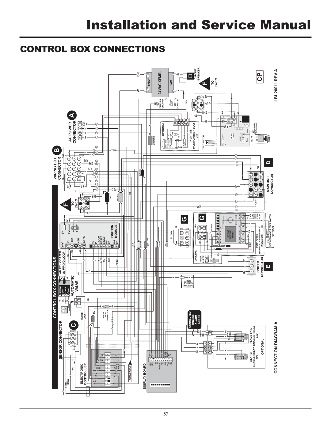
CONTROL BOX CONNECTIONS


WIRING BOX

B


T


SENSOR CONNECTOR

2

Y

1 24Com

VALVE LOCATED

-

+


F1


CONNECTOR


1

BL

2 24V

IN PIPING LOOP


BK


F


BL


T/W


PR/BK


3

4

W/R

3 Close

5


BR/W

PR


4

5

6


P

4 Open

GY


S1


F2

BK


BR


T


AC POWER

A


W


C


3

4

AUTOMATIC


3


/W


TO


/W

1

4

7

10

13


BR


1

2

3


BK

LINE

-


T

2

5

8

11

14


CONNECTOR


4


W


1

2

VALVE

GY

W

2

NEU

+

BK


LWCO


3

6

9

12

15


1

2

3

4


ELECTRONIC


CLOSE


3


1

O/


1

S2/FS


BK


CONTROLLER


OPEN


GY


PR 6

5

4

W


Y

BL/

P


BK

G

W

BK/


BL


GY


W

9


7


P

BK


W


11


O


O/


P


R


BL


O


TH


BL/


BK


P R

W/R BL P BL R/BK


BL


10


2

8


15

13


R O/W

O/BK BR

BL


PR


BL/W


7

RESET


BK


P


9

PI


3 4 7 5 1 6 9

12 11


14

10

1 2 3 4


Y


8

24COM


24

23

22

21 20 19 18

17

16 15

14

13


ALARM


BL


6

24VAC


DELAY


R


5

MV


CONNECTOR


T/W


4

PS


IGNITION


LINE


Y n/a

n/a

W BR PR BR/W PR/

BK T

R BR/W

Y


3


1 2


9 8 7 6

5

4 3

2

1


Delay

R/BK

PR


M/S


O/


PR/BK


2

MODULE


NEUTRAL

BK


1

FF


HtD


ACTIVE INPUT

BR


ALR


W

BK

-24V COM

BLR/LVR


DISPLAY BOARD


IGN1 12

GY


24V


G


120V


IGN1 11

GY


GROUND


10

P


P1 9


S1 8

R


STG #1


CHASSIS

24VAC XFMR .

S2+

6

BK


SERVICE

7

T


S2- 5

W


OPTIONAL


GROUND


ALR 4

PR/BK


TH


Y


RST1 3

BL/W


P


+24

2

BL


P


24V

COM 1

Y


Y


BL O/W


P


P


T


NOT USED


5

5


24V

Y


O/W


R


Y

4

4


COMMON

Y

BL


OPTIONAL SERVICE-

MAINT


3


2

1


G


R


Y

3

3


NOT


R

2

2


BL


6


5


4


USED


CONNECTED


T


R

1

1


RUNTIME


UNLESS


Y


R


MONITORING RELAY


9


7


CIRCUIT


PR

Y

BL


PR/

ALARM


OPTIONAL


R/


24V


BL

6

5

4


BREAKER


PR/ BK

ADDED


PUMP


BR


6


5

4


G

BK


3


1

4


F


3

2

1

BK


PURGE


3


2

1


TEST SWITCH


6


BL/


ON/OFF


BL


BL


PR


5


BK


3

2

1


SWITCH


O


PR


R


O


TO


BL

L1

N

I1

I2

I3

I4

I5

I6


I7

I8


T

T


T


LWCO


O BL


Y

O

PR R

P


BL


PR


PR

P


P

Y

PR


O.C.

BL/

J3


J1


Y


BL

PR/


PURGE/


BK

6

3


BK


SERVICE


24 VAC


5

2

Y


Y


MAINT.


LWCO

O

4

1

PR


6

2

5

1


7


12

10

13

15


O


Y


O

O/BK

BL BR

BL

T


PR

PR


RESET J2


R


W


GY

G

GY


1 Q1

2

1

Q2 2

1

Q3

2


1

Q4 2


Y


T


1

2 3

J4


O


BL

BR


T


PR


P


ALARM


FLAME FAIL


O/BK


1

2

3


PR


1

4

7

10

13

W


PR

PR


ENABLE RELAY ENABLE RELAY


R/BK

2

5

8

11

14


CHASSIS


CP


24V


24V


IGNITER


PUMP PURGE


ALARM


BK


GROUND


(SERVICE / MAINTENANCE


DELAY


3

6

9

12

15


OPTIONAL


CONNECTOR


INDICATOR)


BL


P


BK


E


O

D


N.O.

MAIN UNIT

RESET

SERVICE/MAINT. RESET SWITCH

CONNECTION DIAGRAM A

OPTIONAL

CONNECTOR


LBL20011 REV A


CONTROL BOX CONNECTIONS

Installation and Service Manual

Page 57
Image 57
Lochinvar F0600187510 service manual Control BOX Connections

F0600187510 specifications

The Lochinvar F0600187510 stands out as a premium combination boiler that caters to the heating and hot water needs of residential properties. Known for its energy efficiency and advanced technology, this model is ideal for homeowners seeking both comfort and cost savings.

One of the primary features of the Lochinvar F0600187510 is its exceptional energy efficiency. With an impressive AFUE (Annual Fuel Utilization Efficiency) rating, this boiler redefines performance standards, effectively converting a high percentage of the energy it consumes into usable heat. This not only helps in reducing energy bills but also contributes to lower carbon emissions, making it an environmentally responsible choice.

The F0600187510 is equipped with Lochinvar's advanced control system, which allows for precise temperature regulation. This system includes a user-friendly digital display, enabling homeowners to easily adjust settings for their specific heating and hot water requirements. The boiler also offers weather compensation features that optimize performance based on outdoor temperatures, ensuring maximum efficiency throughout the year.

In terms of hot water production, this model features a built-in indirect water heater design, which provides an abundant supply of domestic hot water on demand. This is ideal for households with high hot water usage, as the system can deliver multiple gallons per minute without interruption.

Moreover, the compact design of the Lochinvar F0600187510 allows for flexible installation options, making it suitable for various settings, including tight spaces. Its robust construction ensures durability and reliability, giving homeowners peace of mind regarding long-term performance.

Safety is another significant characteristic of this combination boiler. It comes with multiple built-in safety features, including flame detection, pressure sensors, and overheat protection, ensuring the system operates securely and efficiently.

Finally, the Lochinvar F0600187510 is backed by a solid warranty, providing homeowners with additional assurance of quality and support. Overall, this boiler represents a harmonious blend of innovative technology, efficiency, and reliability, making it a top choice for modern residential heating and hot water solutions.