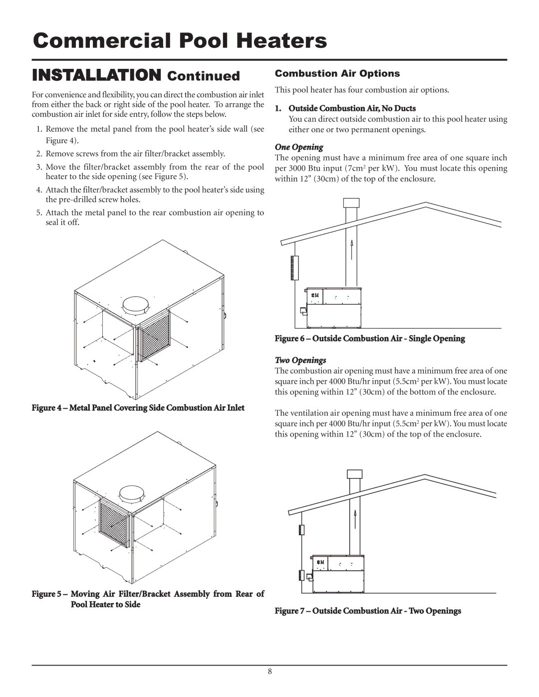
F0600187510 specifications
The Lochinvar F0600187510 stands out as a premium combination boiler that caters to the heating and hot water needs of residential properties. Known for its energy efficiency and advanced technology, this model is ideal for homeowners seeking both comfort and cost savings.One of the primary features of the Lochinvar F0600187510 is its exceptional energy efficiency. With an impressive AFUE (Annual Fuel Utilization Efficiency) rating, this boiler redefines performance standards, effectively converting a high percentage of the energy it consumes into usable heat. This not only helps in reducing energy bills but also contributes to lower carbon emissions, making it an environmentally responsible choice.
The F0600187510 is equipped with Lochinvar's advanced control system, which allows for precise temperature regulation. This system includes a user-friendly digital display, enabling homeowners to easily adjust settings for their specific heating and hot water requirements. The boiler also offers weather compensation features that optimize performance based on outdoor temperatures, ensuring maximum efficiency throughout the year.
In terms of hot water production, this model features a built-in indirect water heater design, which provides an abundant supply of domestic hot water on demand. This is ideal for households with high hot water usage, as the system can deliver multiple gallons per minute without interruption.
Moreover, the compact design of the Lochinvar F0600187510 allows for flexible installation options, making it suitable for various settings, including tight spaces. Its robust construction ensures durability and reliability, giving homeowners peace of mind regarding long-term performance.
Safety is another significant characteristic of this combination boiler. It comes with multiple built-in safety features, including flame detection, pressure sensors, and overheat protection, ensuring the system operates securely and efficiently.
Finally, the Lochinvar F0600187510 is backed by a solid warranty, providing homeowners with additional assurance of quality and support. Overall, this boiler represents a harmonious blend of innovative technology, efficiency, and reliability, making it a top choice for modern residential heating and hot water solutions.

