Manuals
/
Lochinvar
/
Household Appliance
/
Water Heater
Lochinvar
operation manual
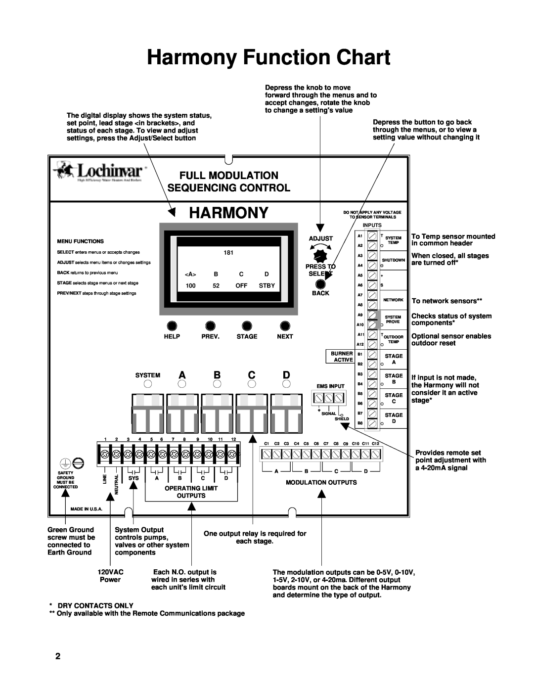
Harmony Function Chart, Full Modulation, Sequencing Control
Models:
Harmony
1
2
32
32
Download
32 pages
16.53 Kb
1
2
3
4
5
6
7
8
Page 2
Image 2
Page 1
Page 3
Page 2
Image 2
Page 1
Page 3
Contents
HARMONY
TABLE OF CONTENTS
Lochinvar
FULL MODULATION
Harmony Function Chart
HARMONY
SEQUENCING CONTROL
Harmony Overview
INPUT WIRING
INSTALLATION
INPUT WIRING
WIRING THE POWER
WIRING THE SYSTEM PROVE
INSTALLATION INPUT WIRING
WIRING THE SHUTDOWN
EMS Sourcing Current
Dry Contact
WIRING THE BOILER ACTIVE INPUTS
Signal
System Prove
CONNECTING AN OUTDOOR SENSOR
OUTPUT WIRING
WIRING A SETBACK
EMS INPUT
System Output Operation in Reset Mode
WIRING THE SYSTEM OUTPUT
WIRING THE STAGE OUTPUTS
Wiring the SYS Output
WIRING TO VOLTAGE MODULATING MOTORS
OUTPUT WIRING
WIRING TO 4-20MA MODULATING MOTORS
INSTALLATION
CHANGING SETTINGS
USING THE MENUS
USING MENUS
MAKING SELECTIONS
SELECTING THE SENSOR TYPE
SYSTEM STARTUP
STARTUP SEQUENCE
Default - F
SELECTING THE OUTPUT TYPE
EMS INPUT Default - Setback
SELECTING THE MODULATING MODE Default - Normal
Not available for Reset Sensor Types
Press to select Normal or turn to scroll down
SELECTING THE OPERATING MODE Default - Normal
SYSTEM STARTUP
Press to select Process
SET POINT
OPERATING SETTINGS
RESET F AND RESET C
THE MAIN DISPLAY
GAIN/THROTTLE
Default =
THROTTLE
PROCESS GAIN/THROTTLING RANGE TABLE
Used to manually change the lead stage
LEAD STAGE
LEAD STAGE
SYSTEM SETTINGS
SYSTEM SETTINGS
SETTINGS
THE SYSTEM SETTINGS MENU
LAG DELAY
PURGE DELAY Default - 1.0 min
Default - 0 min
SYSTEM SETTINGS
Default
STANDBY TIME Default - 10 min
SYSTEM RUN-ONDefault - 0 min
SETBACK
ROTATE TIME
Default 24hr
Default
LAST STAGE HOLD
SET TIME
PASSWORD
Default Disabled
SYSTEM SETTINGS
Default - OFF
STAGE SETTINGS
INDIVIDUAL STAGE ADJUSTMENTS THE STAGE MENU
MODE
STAGE SETTINGS
IGNITION POINT Default - 1%
MODULATION START Default - 75%
Press to show setting Turn to adjust value
Modulating Mode - PARALLEL
COPY SETTINGS - STAGE A ONLY
STAGE SETTINGS
Default
RESET SETTINGS
RESET RATIO
OFFSET Default
MINIMUM WATER TEMPERATURE Default 70F
RESET
Default 64F
OUTDOOR CUTOFF
TEMPERATURE INPUTS
TROUBLESHOOTING
TROUBLESHOOTING
STAGE OUTPUTS
EXTERNAL SET POINT 4-20MA EMS-CONTROLRANGE
APPENDIX
SYSTEM STARTUP MENU
APPENDIX
APPENDIX
MOVING AROUND THE STAGES MENUS
MANUAL CONVENTIONS
Index
Symbols
INDEX
INDEX
4-20mAExternal Input
HARMONY SPECIFICATIONS
Lead Stage Rotation
Top
Page
Image
Contents