NUMBER OF BOILERS USED FOR DHW GENERATION
The number of boilers used for DHW generation can be selected from one to the maximum number of boilers using the BOIL DHW setting. This applies when only a DHW Demand is present. If there are other demands present, the control does not limit the number of boilers operated.
SECTION E2: DHW WITH LOW TEMPERATURE BOILERS
If DHW is to be incorporated into a low temperature system such as a radiant heating system, a mixing device is often installed to isolate the high DHW supply temperature from the lower system temperature. If a mixing device is not installed, high temperature water could be supplied to the low temperature system while trying to satisfy the DHW demand. This may result in damage to the low temperature heating system. The control is capable of providing DHW in such a system while maximizing the chance that the tem- perature in the heating system does not exceed its allowed maximum setting.
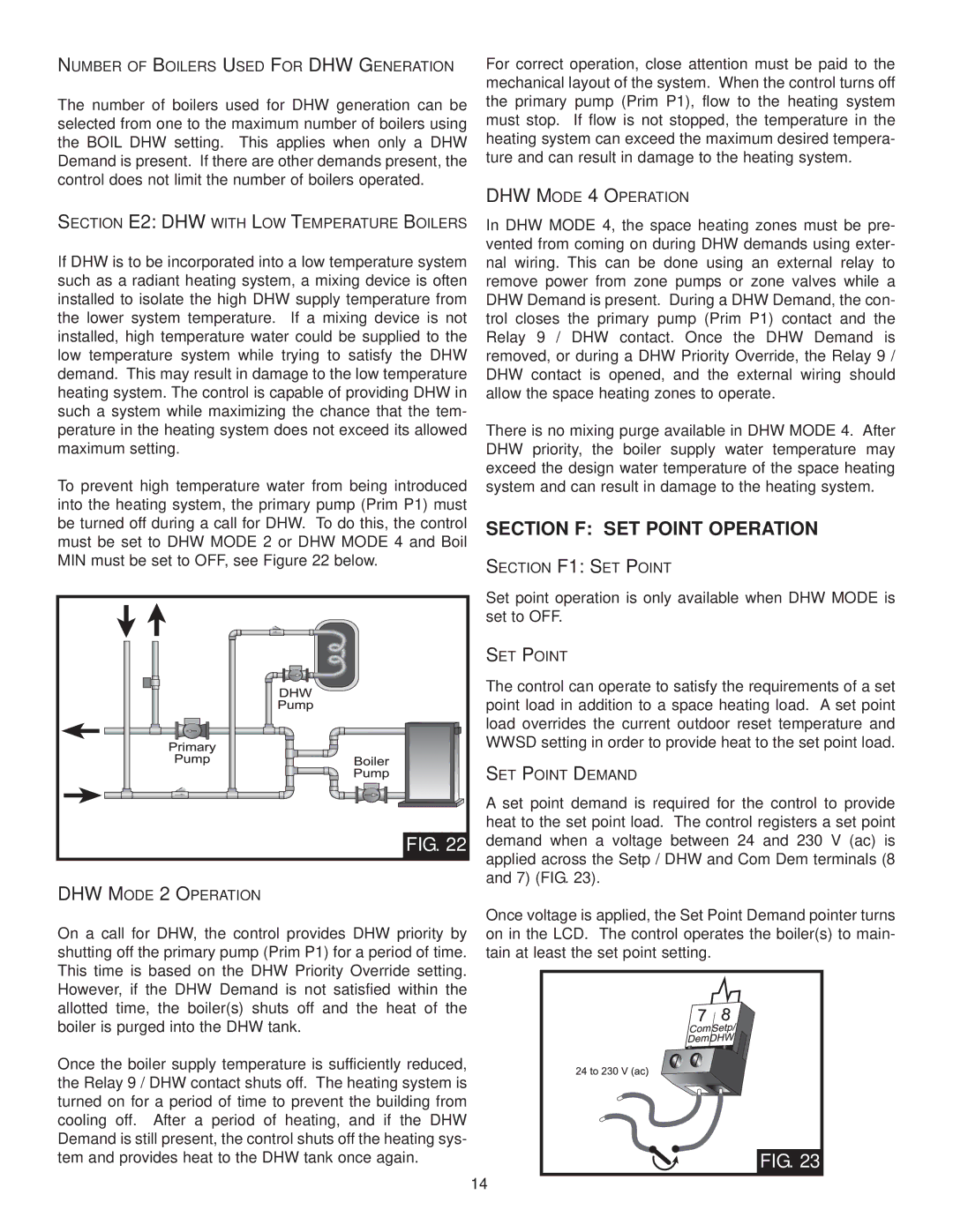
To prevent high temperature water from being introduced into the heating system, the primary pump (Prim P1) must be turned off during a call for DHW. To do this, the control must be set to DHW MODE 2 or DHW MODE 4 and Boil MIN must be set to OFF, see Figure 22 below.
FIG. 22
DHW MODE 2 OPERATION
On a call for DHW, the control provides DHW priority by shutting off the primary pump (Prim P1) for a period of time. This time is based on the DHW Priority Override setting. However, if the DHW Demand is not satisfied within the allotted time, the boiler(s) shuts off and the heat of the boiler is purged into the DHW tank.
Once the boiler supply temperature is sufficiently reduced, the Relay 9 / DHW contact shuts off. The heating system is turned on for a period of time to prevent the building from cooling off. After a period of heating, and if the DHW Demand is still present, the control shuts off the heating sys- tem and provides heat to the DHW tank once again.
For correct operation, close attention must be paid to the mechanical layout of the system. When the control turns off the primary pump (Prim P1), flow to the heating system must stop. If flow is not stopped, the temperature in the heating system can exceed the maximum desired tempera- ture and can result in damage to the heating system.
DHW MODE 4 OPERATION
In DHW MODE 4, the space heating zones must be pre- vented from coming on during DHW demands using exter- nal wiring. This can be done using an external relay to remove power from zone pumps or zone valves while a DHW Demand is present. During a DHW Demand, the con- trol closes the primary pump (Prim P1) contact and the Relay 9 / DHW contact. Once the DHW Demand is removed, or during a DHW Priority Override, the Relay 9 / DHW contact is opened, and the external wiring should allow the space heating zones to operate.
There is no mixing purge available in DHW MODE 4. After DHW priority, the boiler supply water temperature may exceed the design water temperature of the space heating system and can result in damage to the heating system.
SECTION F: SET POINT OPERATION
SECTION F1: SET POINT
Set point operation is only available when DHW MODE is set to OFF.
SET POINT
The control can operate to satisfy the requirements of a set point load in addition to a space heating load. A set point load overrides the current outdoor reset temperature and WWSD setting in order to provide heat to the set point load.
SET POINT DEMAND
A set point demand is required for the control to provide heat to the set point load. The control registers a set point demand when a voltage between 24 and 230 V (ac) is applied across the Setp / DHW and Com Dem terminals (8 and 7) (FIG. 23).
Once voltage is applied, the Set Point Demand pointer turns on in the LCD. The control operates the boiler(s) to main- tain at least the set point setting.
FIG. 23 |
14